

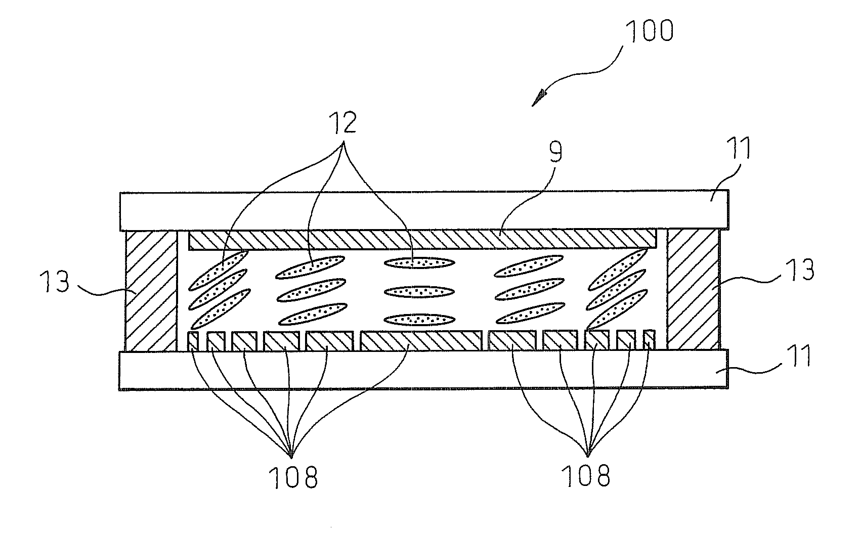
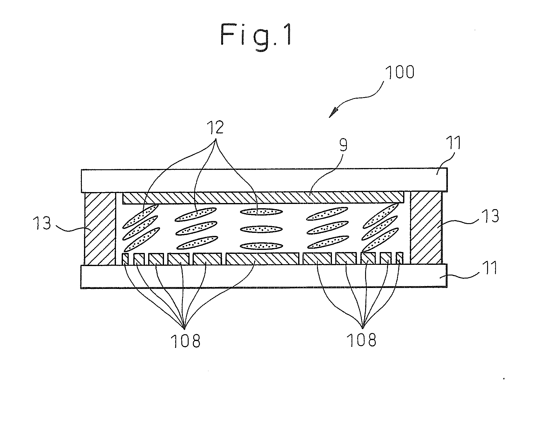
Liquid crystal fresnel lens
a liquid crystal lens and lens body technology, applied in the field of liquid crystal fresnel lenses, can solve the problems of lens focusing performance deformation, and achieve the effects of high focusing performance, easy variation of focal length, and good visibility
- Summary
- Abstract
- Description
- Claims
- Application Information
AI Technical Summary
Benefits of technology
Problems solved by technology
Method used
Image

Examples
example 1
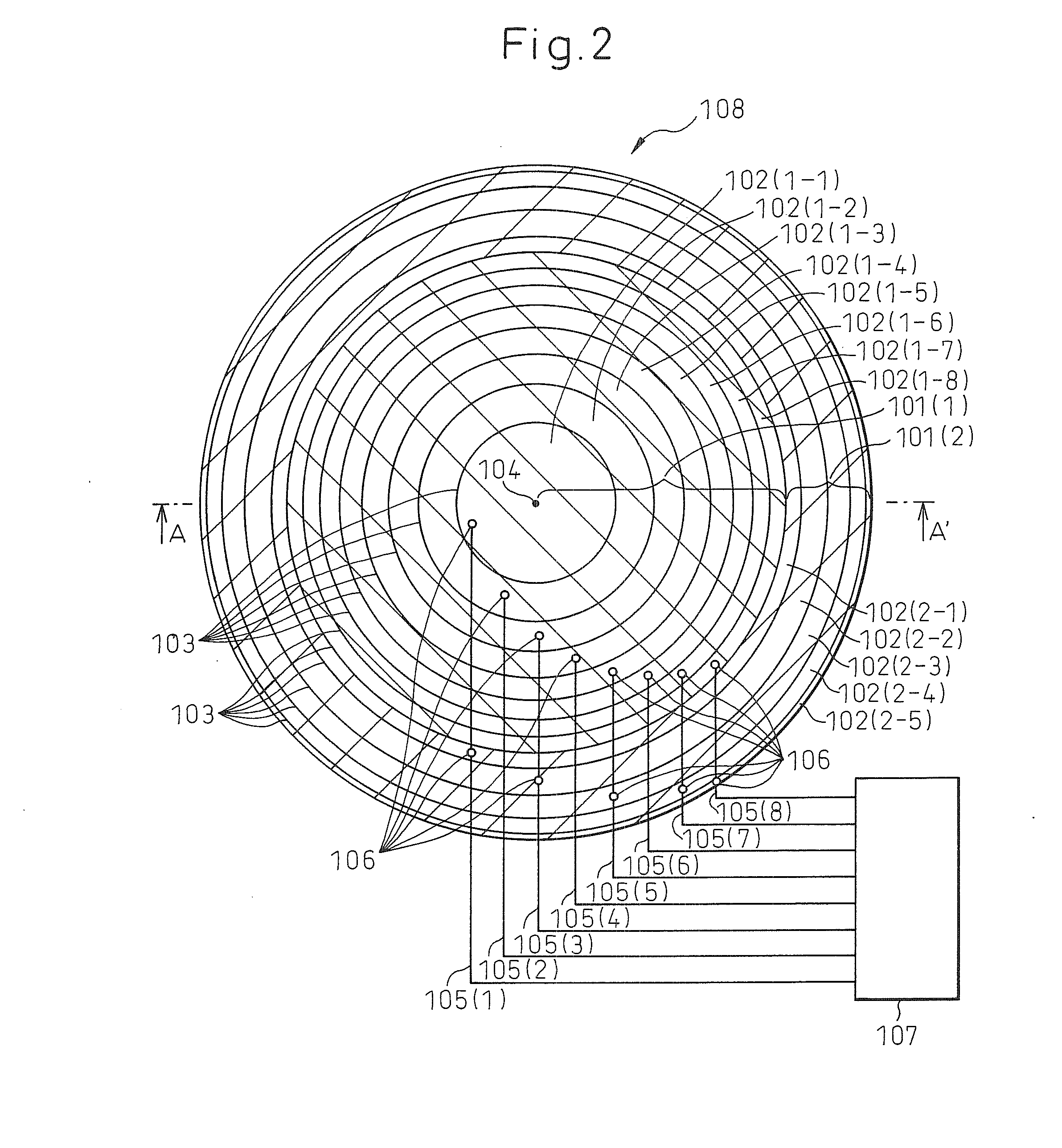
[0071]FIGS. 8 and 9 show a design example of the liquid crystal Fresnel lens according to the present invention that achieves 2.5 diopters under the following conditions: the diameter is 15 mm, the birefringence Δn of the provided homogeneous liquid crystal is 0.25, and the thickness of the liquid crystal layer is 20 μm. The relationship between the applied voltage and the resulting retardation in the liquid crystal used in this example is the same as that shown in FIG. 7.
[0072]To achieve 2.5 diopters, a retardation of about 140000 nm would be required. Further, since the retardation achievable with the liquid crystal layer of 20-μm thickness is about 3000, the number of lens segments was chosen to be 47, and the lens was designed so that a retardation of about 140000 nm could be obtained with the 47 lens segments.
[0073]If the liquid crystal Fresnel lens were fabricated with 47 lens segments, the radius of the largest lens segment located in the center would be about 1.1 mm, and the...
PUM
| Property | Measurement | Unit |
|---|---|---|
| thickness | aaaaa | aaaaa |
| radius | aaaaa | aaaaa |
| diameter | aaaaa | aaaaa |
Abstract
Description
Claims
Application Information