Method for Calibrating the Position of a Laser Fan Beam Relative to the Projection Geometry of an X-Ray Device and X-Ray Device

Active Publication Date: 2010-09-30
SIEMENS HEATHCARE GMBH
View PDF3 Cites 16 Cited by
  • Summary
  • Abstract
  • Description
  • Claims
  • Application Information

AI Technical Summary

Benefits of technology

[0005]The object of the present invention is to provide a method which makes it possible to record the location of the laser or of the laser fan

Problems solved by technology

These torsions lead to unknown projection geometry and location of the laser positioning device.
Also, after the x-ray device has been in operation for a long period, the laser fan beams that were originally adjusted when the x-ray device was installed get out of adjustment.
In particular vibrations ca

Method used


Image

  • Method for Calibrating the Position of a Laser Fan Beam Relative to the Projection Geometry of an X-Ray Device and X-Ray Device
  • Method for Calibrating the Position of a Laser Fan Beam Relative to the Projection Geometry of an X-Ray Device and X-Ray Device
  • Method for Calibrating the Position of a Laser Fan Beam Relative to the Projection Geometry of an X-Ray Device and X-Ray Device

Examples


Embodiment Construction

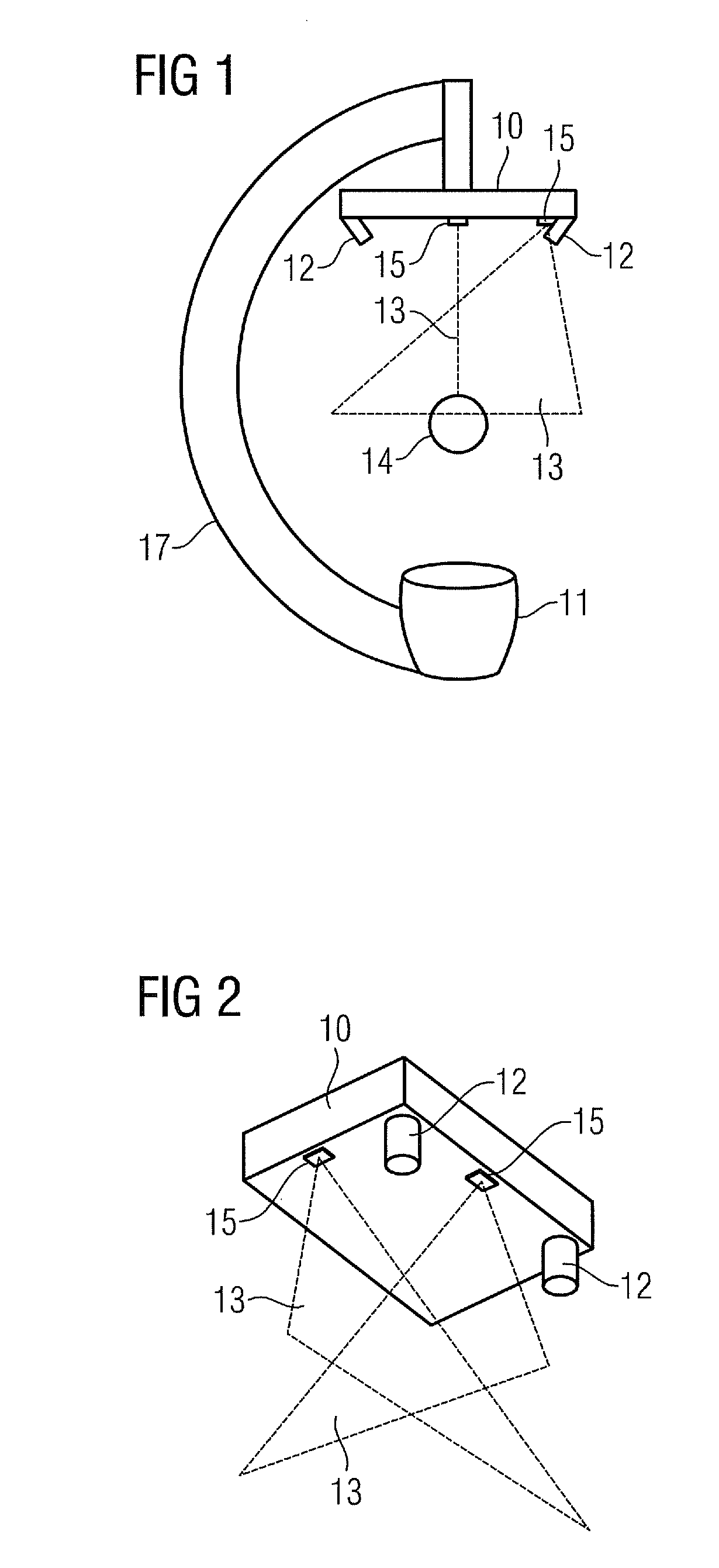
[0029]Sections of the inventive x-ray device are shown in FIG. 1 and FIG. 2, in which an x-ray detector 10 and an x-ray source 11 are arranged on an adjustable, movable 17. The C-arm 17 is preferably adjustable in three dimensions, for example in that it is attached to a multi-axis articulated-arm robot. Arranged on the x-ray detector are two lasers 15 embodied as positioning facilities for instruments, which each generate a laser fan beam 13 along the beam direction of the x-ray beam. The laser fan beans form a laser cross for instrument positioning. The positioning of instruments by means of laser fan beams and laser crosses is known. In addition two cameras 12 are arranged on the x-ray detector 10 which are aligned in the direction of the laser fan beams. Ideally the cameras 12 are arranged at different ends of the x-ray detector 10 in order to be able to reconstruct 3D structures as well as possible with the largest possible spacing. The inventive method can however also be carr...


PUM


Abstract

For detecting the relative location of a laser or laser fan beam relative to the x-ray geometry of an x-ray device, a method for calibrating the position of the laser fan beam generated by a laser in relation to the projection geometry of the x-ray device is proposed. The x-ray device comprises an x-ray imaging system featuring an x-ray source and an x-ray detector. The x-ray source, the x-ray detector, the laser, and an imaging facility are arranged on a support. An optical x-ray calibration phantom is used for the calibration. The position of the imaging facility relative to the projection geometry is determined. The position of the laser fan beam relative to the imaging facility is determined. The position of the laser fan beam relative to the projection geometry is reconstructed.

Description

CROSS REFERENCE TO RELATED APPLICATIONS[0001]This application claims priority of German application No. 10 2009 014 154.5 filed Mar. 24, 2009, which is incorporated by reference herein in its entirety.FIELD OF THE INVENTION[0002]The invention relates to a method for calibrating the position of at least on laser fan beam generated by a laser relative to the projection geometry of an x-ray device and also to an x-ray device for carrying out a method of this type as claimed in the claims.BACKGROUND OF THE INVENTION[0003]In new x-ray devices with C-arms adjustable in three dimensions for supporting x-ray imaging systems, as well as the pure x-ray imaging, positioning devices for positioning tools such as puncturing needles by means of laser fan beams generated by lasers are also used. As a result of their construction C-arms twist depending on the angulation selected. These torsions lead to unknown projection geometry and location of the laser positioning device. These devices are neede...

Claims


Application Information

Patent Timeline
IPC IPC(8): G01D18/00G06K9/00
CPCA61B6/4441A61B6/547A61B2019/5255A61B2019/5242A61B6/583A61B2090/3764A61B2034/2055
Inventor HEIGL, BENNOLAUTENSCHLAGER, STEFANMOLLER, THOMAS
Owner SIEMENS HEATHCARE GMBH
Why Eureka
Try Eureka