Method and apparatus of measuring positional variation of rotation center line

a technology of rotation center line and measurement method, which is applied in the direction of metal-working machine components, instruments, manufacturing tools, etc., can solve the problems of high accuracy and difficulty in obtaining measurement, and achieve the effect of reducing the amount of rotation center line positional variation, no fear of errors, and high accuracy

Inactive Publication Date: 2010-09-30
FUJI PHOTO OPTICAL CO LTD
View PDF3 Cites 7 Cited by
  • Summary
  • Abstract
  • Description
  • Claims
  • Application Information

AI Technical Summary

Benefits of technology

[0008]The invention has been made in view of such the circumstances, and an object of the invention is to provide a method and an apparatus of measuring positional variation of a rotation center line, which are capable of measuring the positional variation of the rotation center line accompanied with the rotation of a sample with high accuracy.
[0012]According to the method and the apparatus of measuring the positional variation of the rotation center line of the invention, by providing the above-mentioned constitution, the following advantage is obtained.
[0013]Namely, the movement locus of the position indicator set in the sample becomes circular in case that there is no positional variation of the rotation center line, and becomes, in case that there is the positional variation, the shape out of the circle in response to the variation amount. In the invention, since the magnified image of the position indicator is picked up by means of the microscope, and the movement locus of the position indicator is found on the basis of this magnified image, the even tiny variation of the movement locus may be captured. Accordingly, it is possible to obtain the positional variation amount of the rotation center line with the high accuracy.
[0014]Further, in the invention, the microscope is used as the only measurement system, which is different from the method in which the plural displacement meters is used as each measurement system. Therefore, there is no fear of errors caused by difference in property between the measurement systems.

Problems solved by technology

However, since the plural displacement meters is used, in case that there are differences in property (for example, temperature property) between the displacement meters, errors caused by the differences in the property are produced between the measurement data of the displacement meters, with the result that it is difficult to obtain the measurement results having high accuracy.

Method used


Image

  • Method and apparatus of measuring positional variation of rotation center line
  • Method and apparatus of measuring positional variation of rotation center line
  • Method and apparatus of measuring positional variation of rotation center line

Examples


Embodiment Construction

[0022]An embodiment of the invention will be described below in detail with reference to the above drawings. Each figure used in description of the embodiment does not show the detailed shape and structure of the invention, but the size of each member and distance between the members have been appropriately changed in each figure.

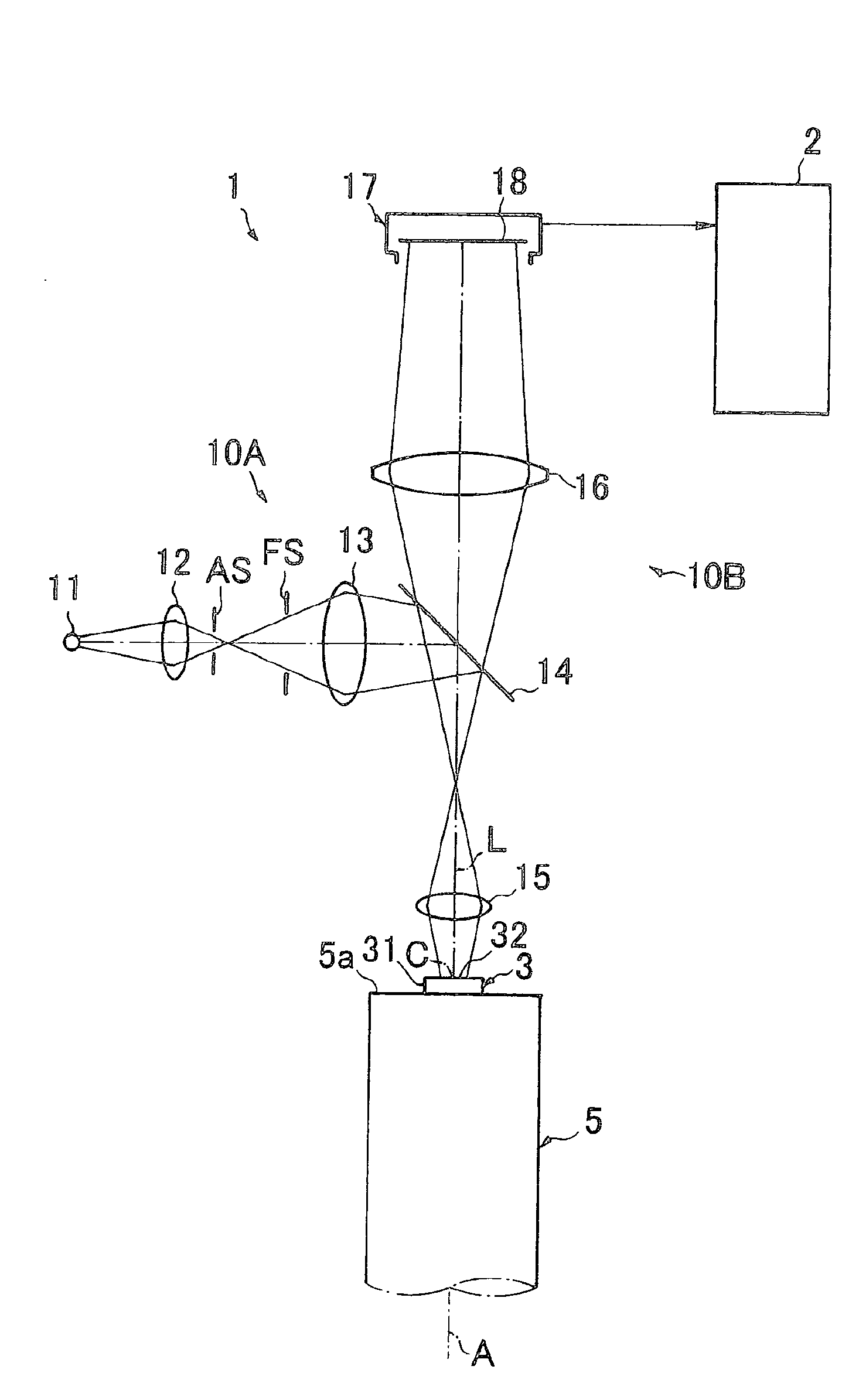
[0023]An apparatus of measuring positional variation of a rotation center line shown in FIG. 1 (which may be hereinafter referred to as an “apparatus in this embodiment”) is used to measure and analyze the positional variation amount of a rotation center line A of a sample 5 (for example, a main spindle of a lathe machine) accompanied with the rotation of the sample 5, which includes a microscope 1, an analysis device 2 as an analysis unit, and a measurement jig 3 placed and fixed onto a leading end surface 5a of the sample 5. The rotation center line A of the sample 5 is treated as what is fixed to the sample 5, and the leading end surface 5a of the sample...


PUM


Abstract

A measurement jig having a position indicator is set so as to rotate integrally with a sample, and a magnified image of the position indicator formed by a microscope is picked up by an imaging camera at plural time points during the rotation of the sample. A movement locus of the magnified images picked up is founded, and position variation amount of a rotation center line of the sample is calculated on the basis of the found movement locus.

Description

[0001]The present application claims priority from Japanese Patent Application No. 2009-074467 filed on Mar. 25, 2009, the entire content of which is incorporated herein by reference.BACKGROUND OF INVENTION[0002]1. Field of the Invention[0003]The present invention relates to a method and an apparatus of measuring positional variation (run-out) of a rotation center line of one of various types of rotators often used in machine tools, electronic devices, and the like. Particularly, a method and an apparatus suitable to measure the positional variation of a rotation center line of a rotator requiring high rotary accuracy such as a main spindle of a precision machine tool are related.[0004]2. Description of the Related Art[0005]In a precision machine tool, such as a grinding machine, in case that the position of a rotation center line (position in the diameter direction) of a main spindle varies greatly, machining accuracy drops remarkably. Therefore, at the time of delivery and mainten...

Claims


Application Information

Patent Timeline
Patent Type & Authority Applications(United States)
IPC IPC(8): G06K9/62
CPCG01B11/272B23Q17/24
Inventor GE, ZONGTAOTAKAHASHI, KENICHI
Owner FUJI PHOTO OPTICAL CO LTD
Why Eureka
Try Eureka