
Modified Fuel Cell Manifolds for Controlling Fuel Gas Flow to Different Sections of Fuel Cell Stacks

a fuel cell and manifold technology, applied in the direction of fuel cells, fuel cell auxilaries, electrochemical generators, etc., can solve the problems of unpredictability of individual cells in the stacked sequence, inability to predict the operational time period before cell performance deterioration, and inability to predict which cells and how many cells will fail

Inactive Publication Date: 2010-09-30
IRD FUEL CELLS
View PDF5 Cites 6 Cited by
  • Summary
  • Abstract
  • Description
  • Claims
  • Application Information

AI Technical Summary

Benefits of technology

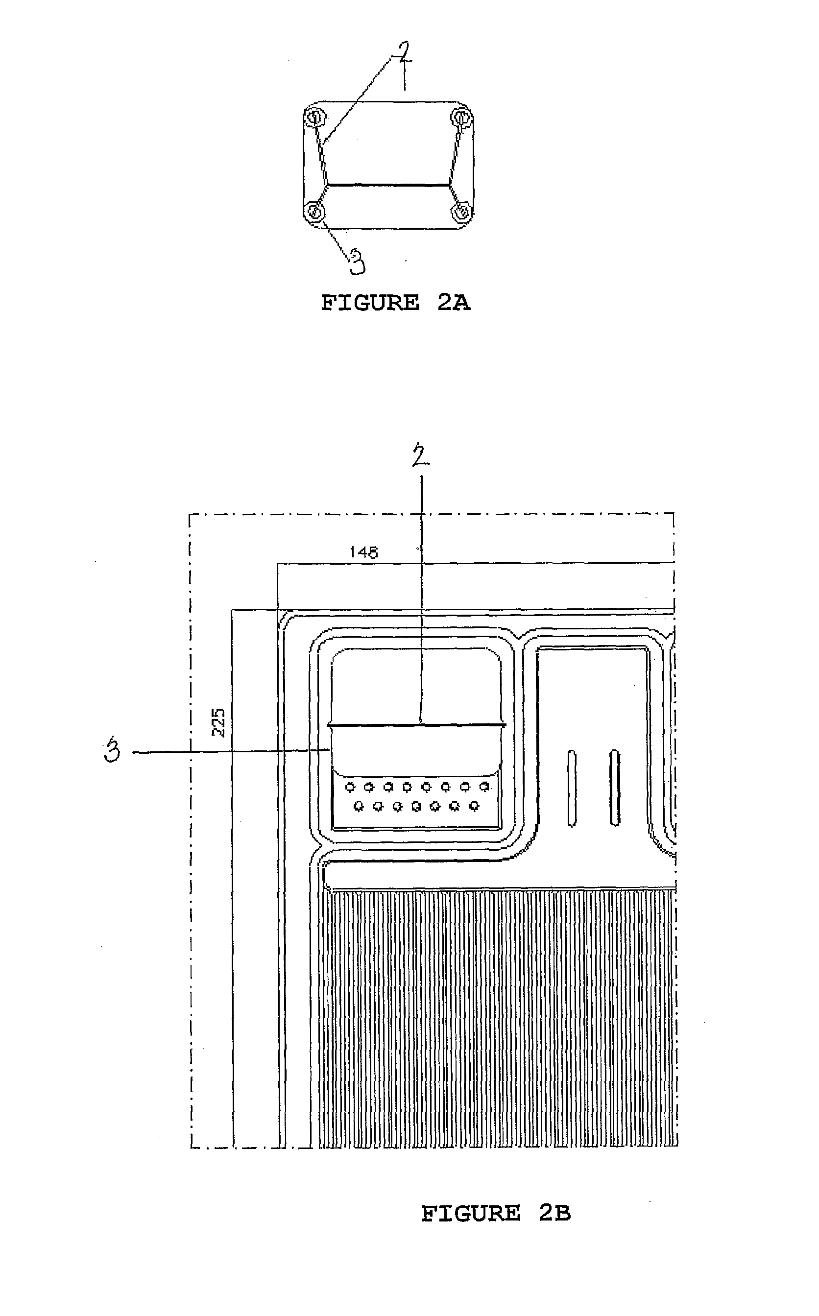
[0012]In another embodiment, a perforated pipe is inserted into the fuel delivery manifold which extends through the stacked fuels cells from the first fuel cell of the stack to the last fuel cell of the stack. The perforated pipe serves as a supply channel for the fuel to each fuel delivery manifold. In this embodiment, the pipe is preferably perforated radially in a stepped pattern so that when it is put under tension the pipe deforms elastically so as to provide a regulated flow path for fuel to pass from the perforated pipe into all sections of the manifold. Also preferred is that the pipe extend beyond the first fuel cell and the last fuel cell of the stack so that it can act as a fixing means in place of the bolts typically used to fix the stack and to provide compression of gaskets and sealing features so that all channels are tightly sealed against fluid loss. In this embodiment of the present invention, each manifold of the fuel cell is enlarged so that perforated pipes can extend through each of the delivery and exit manifolds, thus serving as both supply channels for fuel and air or exhaust channels for reaction products, spent fuel and spent air, as well as the fixing and compression means of the fuel cell stack.

Problems solved by technology

However, in cases where 100% of the hydrogen gas supply is replaced by reformer gas containing, for example, 75% hydrogen and 25% of either nitrogen or carbon dioxide, it has been observed that individual cells in the stacked sequence fail unpredictably after a certain time.
It is not possible to predict the operational time period before cell performance deteriorates, nor is it possible to predict which cell and how many cells will fail.
While single cells perform well and predictably under these conditions, when stacked, one or more cells can become locally depleted of fuel gas on the anode side.
Such an event can lead to permanent damage of the fuel cell stack.
The problem appears to be related to uneven fuel supply on the anode side to certain cells in the fuel cell stack.
In particular the problem appears to affect the downstream cells fed from the common fuel feed manifold.
It is symptomatic that the final cell and its immediate neighbors are prone to fail; the failure pattern being that one of the ultimate cells of the stack fails to maintain flow on the anode side and the cells floods due to the accumulation of water.
Subsequently the proximal cells also seriously suffer from a drop in output and fail.
However, a considerable amount of excess fuel must be made available.
This is wasteful and undesirable.

Method used


Image

  • Modified Fuel Cell Manifolds for Controlling Fuel Gas Flow to Different Sections of Fuel Cell Stacks
  • Modified Fuel Cell Manifolds for Controlling Fuel Gas Flow to Different Sections of Fuel Cell Stacks
  • Modified Fuel Cell Manifolds for Controlling Fuel Gas Flow to Different Sections of Fuel Cell Stacks

Examples


Embodiment Construction

[0017]The present invention provides for design of a modified fuel delivery manifold for use in fuel cells and stacks thereof to provide for careful control of the fuel gas flow in different sections of the fuel cell stack.

[0018]In the fuel cells of the present invention, the fuel delivery manifold is enlarged as compared to the fuel delivery manifold of conventional fuel cells. In a preferred embodiment, the fuel delivery manifold is at least twice the height of a conventional manifold. A typical size for a conventional manifold is 40 mm in width by 15 mm in height. Thus, an exemplary size for the modified fuel delivery manifold of the present invention is 40 mm in width by 30 mm in height. In some embodiments of the present invention, similar size modifications are made to the fuel exit and air delivery and exit manifolds as well.

[0019]The size modification of the fuel delivery manifold of the present invention is made to incorporate a means into the fuel cell delivery manifold wh...


PUM


Abstract

A fuel delivery manifold enlarged in size is provided which, when incorporated into fuel cells which are then stacked allows for insertion of a baffle or a perforated fuel delivery tube through the fuel cell stack via the enlarged fuel delivery manifold to enhance and / or even out or equalize fuel delivery to all fuel cells in the fuel cell stack.

Description

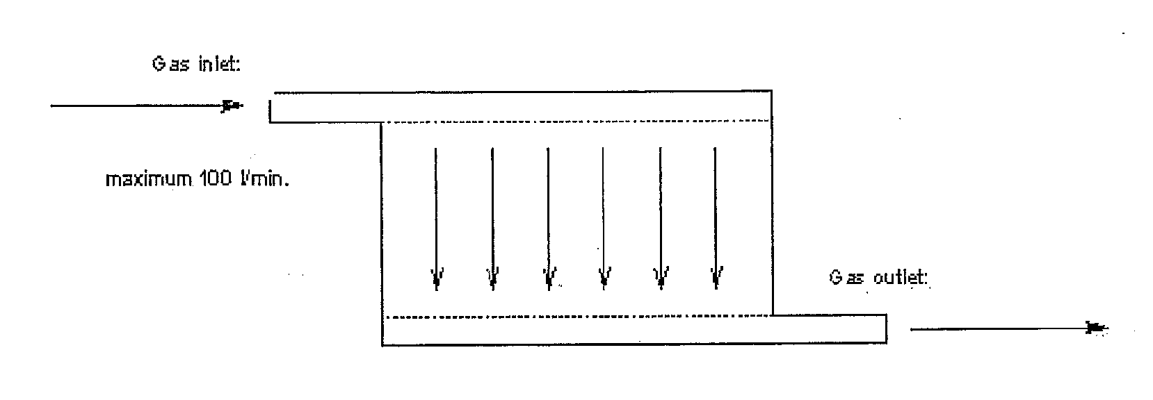
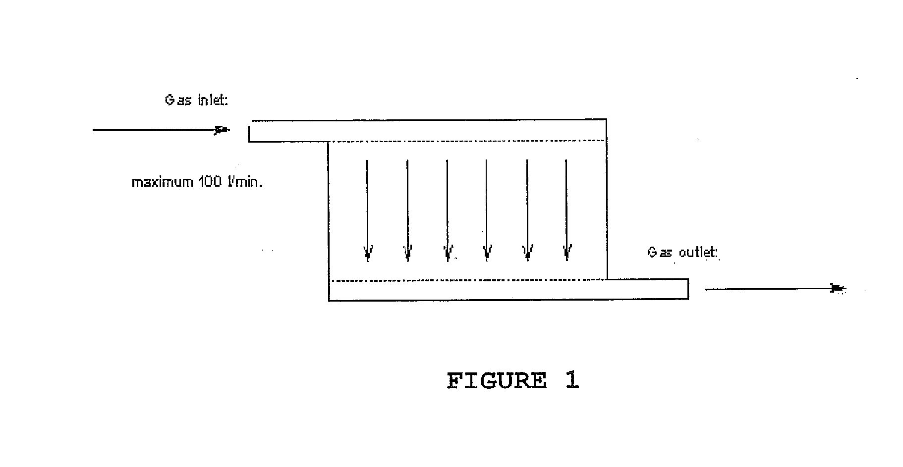
[0001]This patent application claim priority to U.S. Provisional Application Ser. No. 60 / 878,511, filed Jan. 4, 2007, teachings of which are herein incorporated by reference in their entirety.FIELD OF THE INVENTION[0002]The present invention relates to a fuel cell with a fuel delivery manifold modified in size so that, when stacked, a baffle or a perforated fuel delivery tube can be inserted through the fuel cell stack via the modified manifold to enhance and / or even out or equalize fuel delivery to all fuel cells in the fuel cell stack.BACKGROUND OF THE INVENTION[0003]A conventional hydrogen Polymer Electrolyte Membrane (PEM) fuel cell configuration is depicted herein in FIG. 1. In this conventional configuration, the required number of single cells is stacked and the gas supply to each single cell is connected in parallel. Fuel and air required for the electrochemical reaction are fed at the appropriate rate via common manifolds. The direction of the gas flow is arbitrary and is s...

Claims


Application Information

Patent Timeline
IPC IPC(8): H01M8/24H01M8/04
CPCH01M8/241Y02E60/50H01M8/2485H01M8/248H01M8/2483
Inventor FREDERIKSEN, HENNINGLUNDSGAARD, JORGEN SCHJERNING
Owner IRD FUEL CELLS
Learn More