
Receiving apparatus, receiving method, program, and receiving system

a technology of receiving apparatus and receiving method, applied in the direction of coding, code conversion, fault response, etc., can solve the problems that the need has not been met adequately by the candidate receiver, and the desired plp cannot be extracted

Inactive Publication Date: 2010-09-30
SONY SEMICON SOLUTIONS CORP
View PDF5 Cites 56 Cited by
  • Summary
  • Abstract
  • Description
  • Claims
  • Application Information

AI Technical Summary

Benefits of technology

[0016]Where the receiving apparatus, receiving method, and program of the present embodiment are provided as outlined above, the receiving apparatus includes: an LDPC (Low Density Parity Check) decoding device configured such that when an LDPC-coded data signal and an LDPC-coded transmission control signal are transmitted in multiplexed fashion, the LDPC decoding device can decode both the data signal and the transmission control signal; and a holding device configured to be located upstream of the LDPC decoding device and to hold at least the transmission control signal upon receipt of the data signal and the transmission control signal. Control is then exercised by the receiving method or program to have the LDPC decoding device decode the data signal while the transmission control signal is being accumulated in the holding device. Control is further exercised by the receiving method or program to interrupt the current decoding to let the LDPC decoding device decode the transmission control signal when the transmission control signal has been accumulated in the holding device.
[0017]According to another embodiment of the present invention, there is provided a receiving system including: an acquisition device configured to acquire an LDPC-coded data signal, LDPC representing Low Density Parity Check, and an LDPC-coded transmission control signal when these signals are transmitted in multiplexed fashion over a predetermined channel; and a channel decoding device configured to perform a channel decoding process on the signals acquired by the acquisition device over the channel, the channel decoding process at least including a process for correcting errors that may have occurred over the channel, the channel decoding device further outputting the signals thus processed. The receiving system further includes either an information source decode processing device configured to perform an information source decoding process on the signals output from the channel decoding device, or a recording device configured to record the signals output from the channel decoding device to a recording medium. The channel decoding device includes: an LDPC decoding device configured to decode the data signal and the transmission control signal; a holding device configured to be located upstream of the LDPC decoding device and to hold at least the transmission control signal upon receipt of the data signal and the transmission control signal; and a control device configured to control the LDPC decoding device to decode the data signal while the transmission control signal is being accumulated in the holding device and to interrupt the current decoding so as to control the LDPC decoding device to decode the transmission control signal when the transmission control signal has been accumulated in the holding device.
[0018]Where the receiving system of the present embodiment is provided as outlined above, the system includes: an acquisition device configured to acquire an LDPC (Low Density Parity Check)-coded data signal and an LDPC-coded transmission control signal when these signals are transmitted in multiplexed fashion over a predetermined channel; and a channel decoding device configured to perform a channel decoding process on the signals acquired by the acquisition device over the channel, the channel decoding process at least including a process for correcting errors that may have occurred over the channel, the channel decoding device further outputting the signals thus processed. The system further includes either an information source decode processing device configured to perform an information source decoding process on the signals output from the channel decoding device, or a recording device configured to record the signals output from the channel decoding device to a recording medium. The channel decoding device includes an LDPC decoding device configured to decode the data signal and the transmission control signal, and a holding device configured to be located upstream of the LDPC decoding device and to hold at least the transmission control signal upon receipt of the data signal and the transmission control signal. The channel decoding device is arranged to exercise control to have the LDPC decoding device decode the data signal while the transmission control signal is being accumulated in the holding device. The channel decoding device is further arranged to exercise control to interrupt the current decoding to let the LDPC decoding device decode the transmission control signal when the transmission control signal has been accumulated in the holding device.

Problems solved by technology

However, this need has yet to be met adequately by candidate receivers.
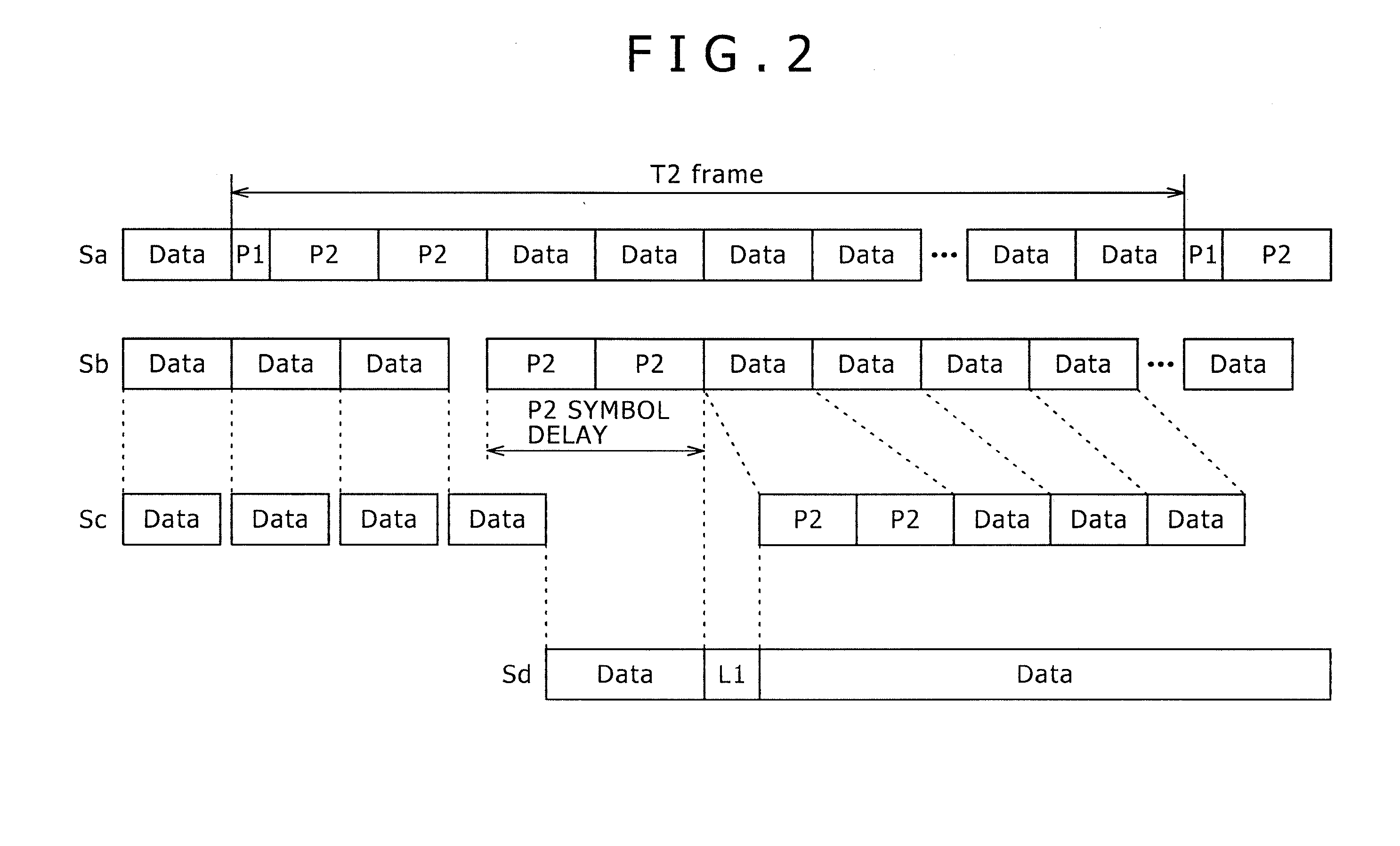
This means that unless L1 is taken, any desired PLP cannot be extracted following a frequency deinterleaving process.

Method used


Image

  • Receiving apparatus, receiving method, program, and receiving system
  • Receiving apparatus, receiving method, program, and receiving system
  • Receiving apparatus, receiving method, program, and receiving system

Examples


Embodiment Construction

Structure of the receiving apparatus complying with DVB-T.2

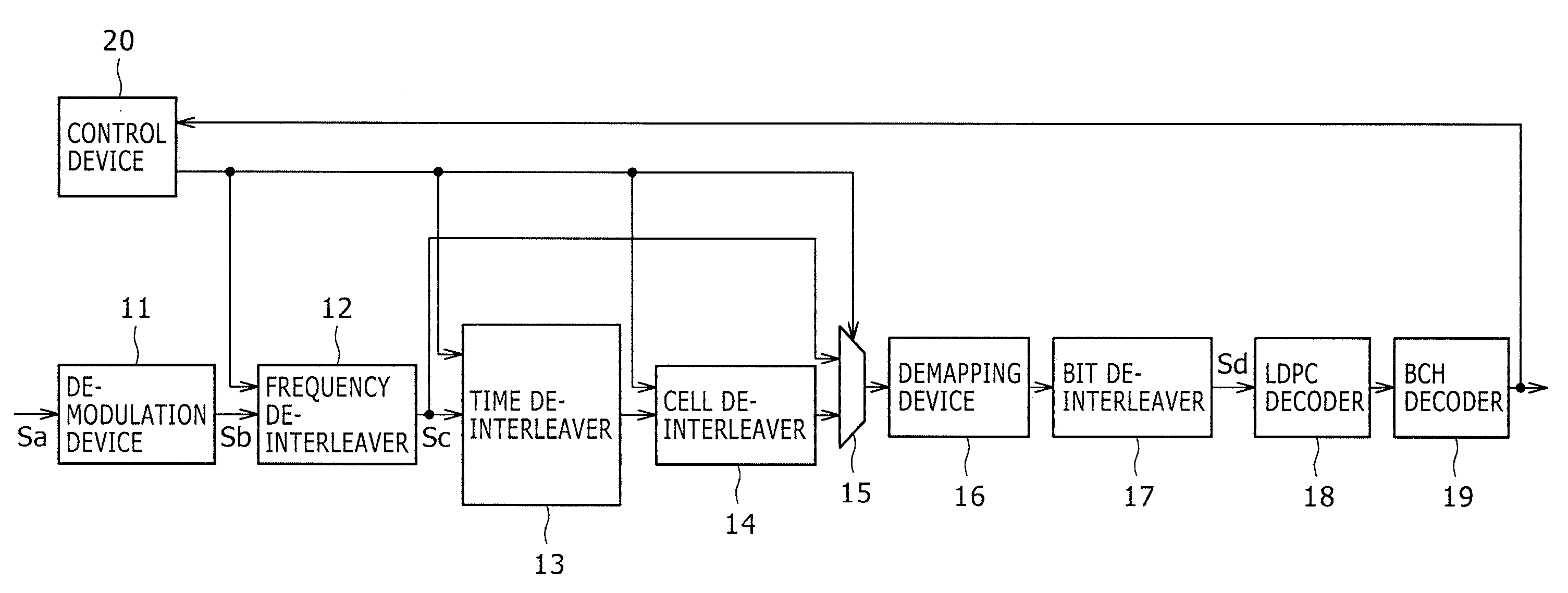
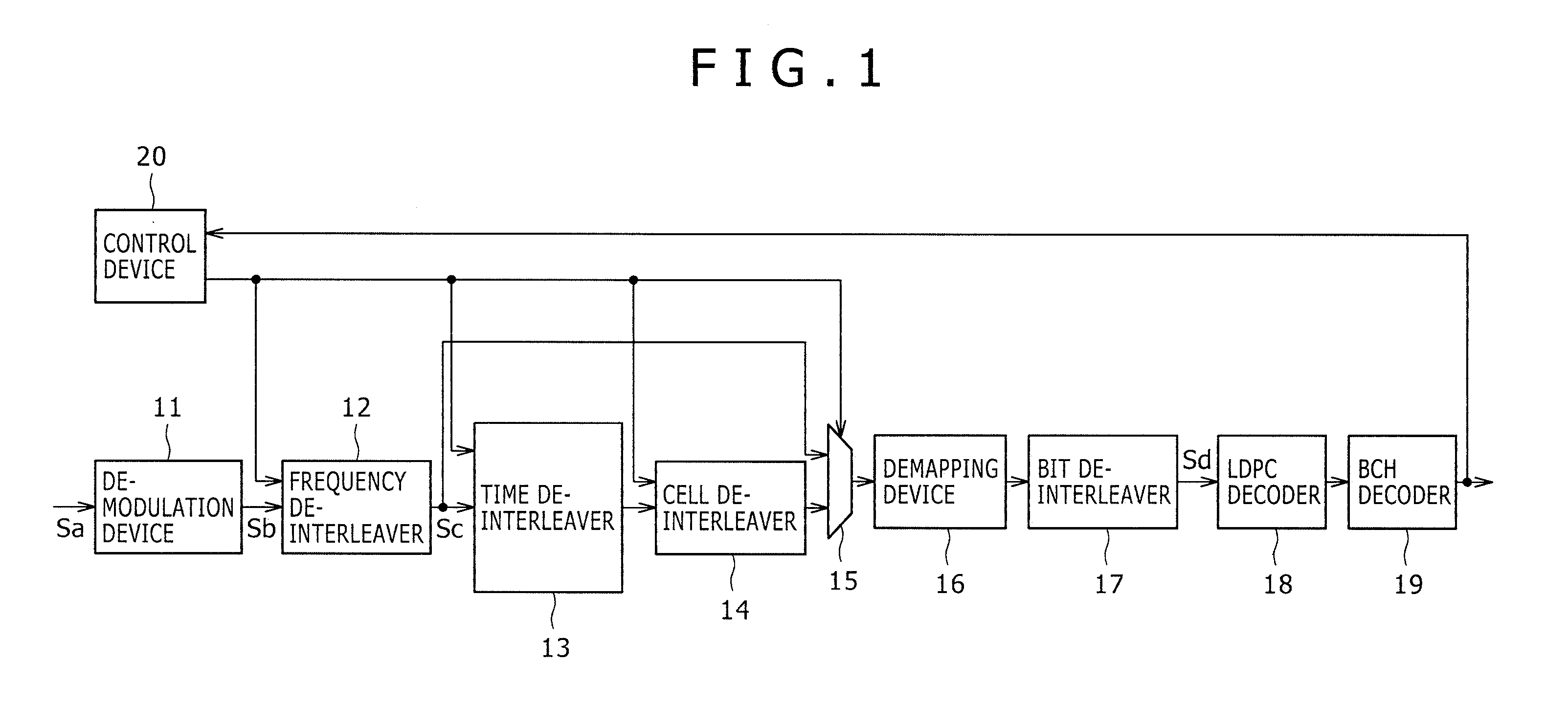
[0029]FIG. 1 schematically shows a typical structure of a receiving apparatus practiced as one preferred embodiment of the present invention.

[0030]In digital broadcasting under DVB-T.2, LDPC codes are turned into symbols of orthogonal modulation (digital modulation) such as QPSK (Quadrature Phase Shift Keying), and these symbols are mapped at constellation points before being transmitted. Illustratively, the receiving apparatus of FIG. 1 adopts OFDM (Orthogonal Frequency Division Multiplexing) as the modulation system for digital broadcasting.

[0031]The receiving apparatus of FIG. 1 functions as a digital broadcast receiving apparatus that complies with DVB-T.2. The DVB-T.2-compatible receiving apparatus is structured to include a demodulation device 11, a frequency deinterleaver 12, a time deinterleaver 13, a cell deinterleaver 14, a switching device 15, a demapping device 16, a bit deinterleaver 17, an LDPC decoder 18, a BC...


PUM


Abstract

A receiving apparatus includes: an LDPC decoding device configured such that when an LDPC-coded data signal, LDPC representing Low Density Parity Check, and an LDPC-coded transmission control signal are transmitted in multiplexed fashion, the LDPC decoding device can decode both the data signal and the transmission control signal; a holding device configured to be located upstream of the LDPC decoding device and to hold at least the transmission control signal upon receipt of the data signal and the transmission control signal; and a control device configured to control the LDPC decoding device to decode the data signal while the transmission control signal is being accumulated in the holding device and to interrupt the current decoding so as to control the LDPC decoding device to decode the transmission control signal when the transmission control signal has been accumulated in the holding device.

Description

BACKGROUND OF THE INVENTION[0001]1. Field of the Invention[0002]The present invention relates to a receiving apparatus, a receiving method, a program, and a receiving system. More particularly, the invention relates to a receiving apparatus, a receiving method, a program, and a receiving system for allowing a DVB-T.2-compatible receiver to carry out LDPC decoding of PLPs and L1 using a single decoder.[0003]2. Description of the Related Art[0004]Communication systems perform reliable communications over noise-plagued communication channels by resorting to coding. For example, wireless systems such as satellite-based networks are exposed to numerous noise sources due to geographical and environmental factors. Such communication channels represent fixed capacities which are defined in terms of the number of bits per symbol at a given signal-to-noise ratio (SNR) and which constitute a theoretical upper limit known as the Shannon limit. As a result, coding design aims at attaining rates ...

Claims


Application Information

Patent Timeline
Patent Type & Authority Applications(United States)
IPC IPC(8): H03M13/05G06F11/10H03M13/27
CPCH03M13/1105H03M13/15H03M13/152H03M13/27H04L2001/0093H03M13/6552H04L1/0057H04L1/0065H04L1/0071H03M13/2906
Inventor YOKOKAWA, TAKASHISHINYA, OSAMU
Owner SONY SEMICON SOLUTIONS CORP
Learn More