Securing Brake Shoes to Brake Beams in a Railroad Car Retarder

a technology for rail cars and brake beams, applied in rail brake actuation, track brakes, railway braking systems, etc., can solve the problems of inability of the installer to torque the bolts connecting the brake shoes to the brake beams to their full theoretical load, and the loosening of the bolts. to the full load

Inactive Publication Date: 2010-10-07
AAA SALES ENG
View PDF17 Cites 11 Cited by
  • Summary
  • Abstract
  • Description
  • Claims
  • Application Information

AI Technical Summary

Benefits of technology

[0009]In accordance with the subject invention, several related solutions to bolt loosening and failure in both types of retarders have been found. In one embodiment, in which the brake shoe spans adjacent end halves of two brake beams, the bolts that connect the brake shoe to the beams are supplemented with large hardened pins which become the main load carrying elements. The bolts function to help seat the pins by drawing the brake shoe and brake beam together and to hold the assembly in place.
[0010]In the other embodiment, in which one brake shoe is attached to and spans the length of a single brake beam, a tongue and groove arrangement on the ends of adjacent brake shoes permits the lead brake shoe, when actuated, to engage and begin to lift the adjacent following shoe to get it moving in the correct direction. This arrangement also reduces considerably the sequential slamming in prior art retarders of this design. The large hardened pins of the embodiment discussed above are also used in this arrangement.

Problems solved by technology

Although some improvement in the decreased bolt loosening has been achieved in both of the foregoing embodiments utilizing pins to carry the main loads, unacceptable bolt loosening and failure continues to be encountered.
A significant cause of this continued problem appears to be in the inability of the installer to torque the bolts connecting the brake shoes to the brake beams to their full theoretical loads.

Method used


Image

  • Securing Brake Shoes to Brake Beams in a Railroad Car Retarder
  • Securing Brake Shoes to Brake Beams in a Railroad Car Retarder
  • Securing Brake Shoes to Brake Beams in a Railroad Car Retarder

Examples


Embodiment Construction

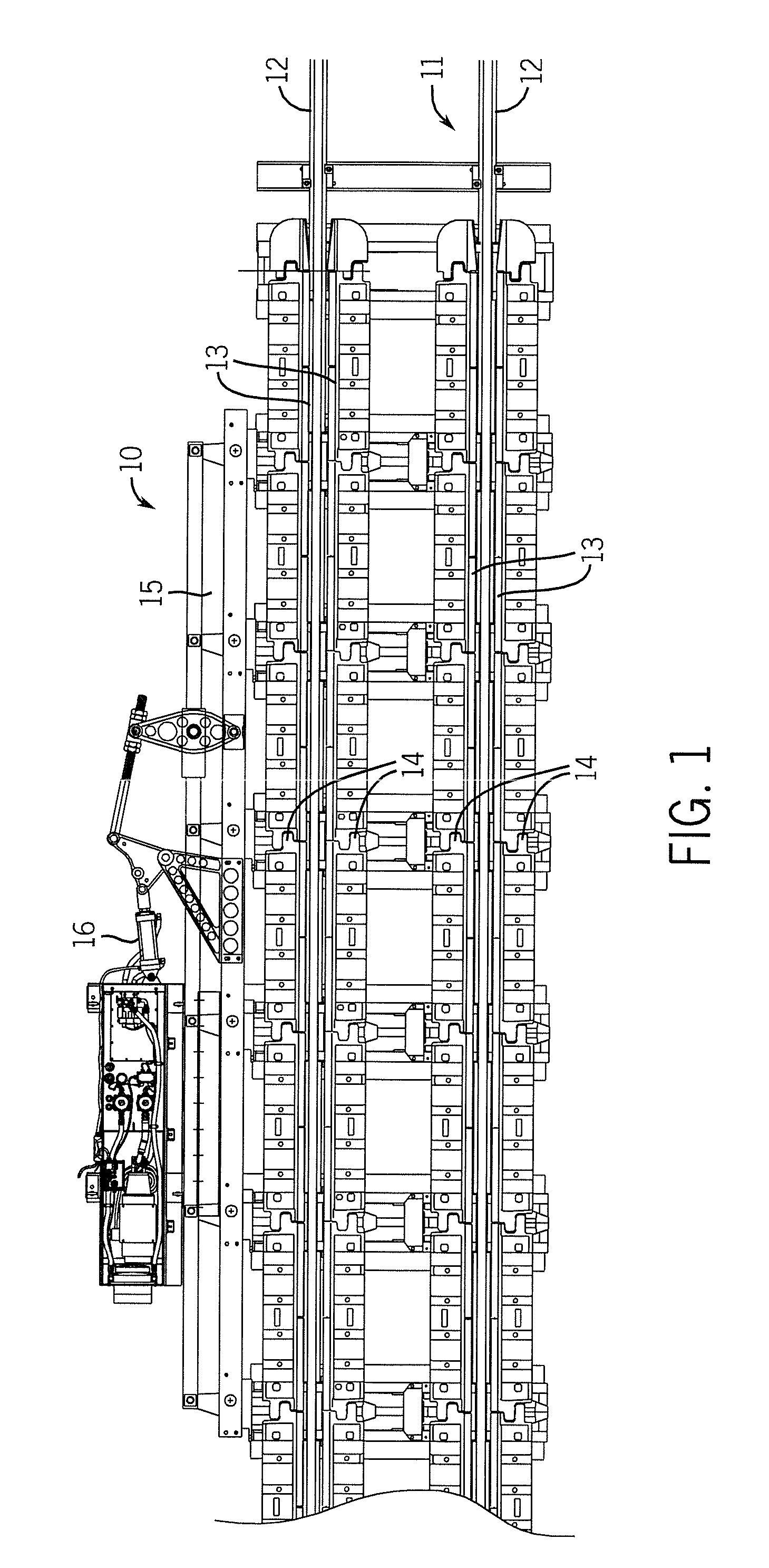
[0026]Referring to FIG. 1, a railroad car retarder 10 is shown mounted along a section of track 11 comprising a pair of conventional rails 12. Track 11 continues in both directions from the retarder with rail cars entering the retarder from one direction, being slowed by the braking action of the retarder, and existing the other end. Each retarder 10 includes linear series of pairs of parallel brake shoes 13 on opposite sides of and parallel to each of the rails 12. The brake shoes are attached to and carried by brake beams 14, which position the brake shoes above the tops of the rails 12 such that, when moved toward one another, the brake shoes engage the sides of the car wheels to effect a braking or retarding of the moving rail car, as is well known in the art.

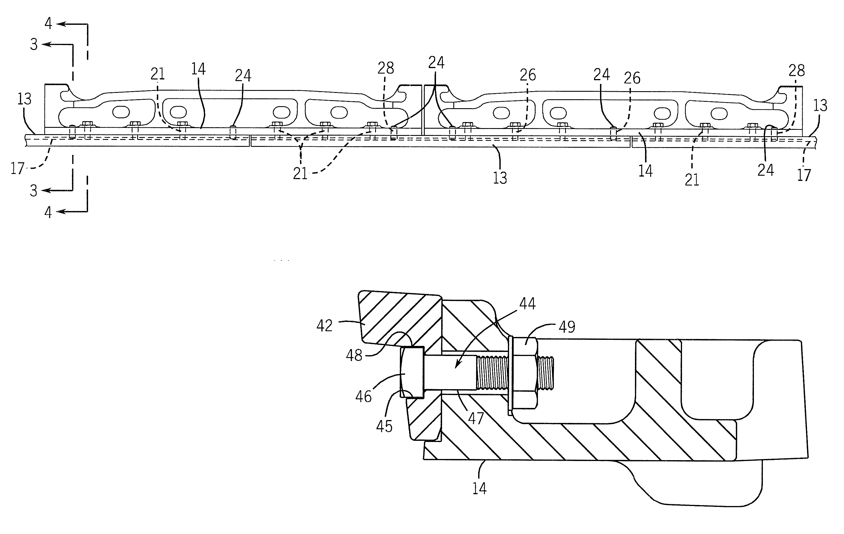
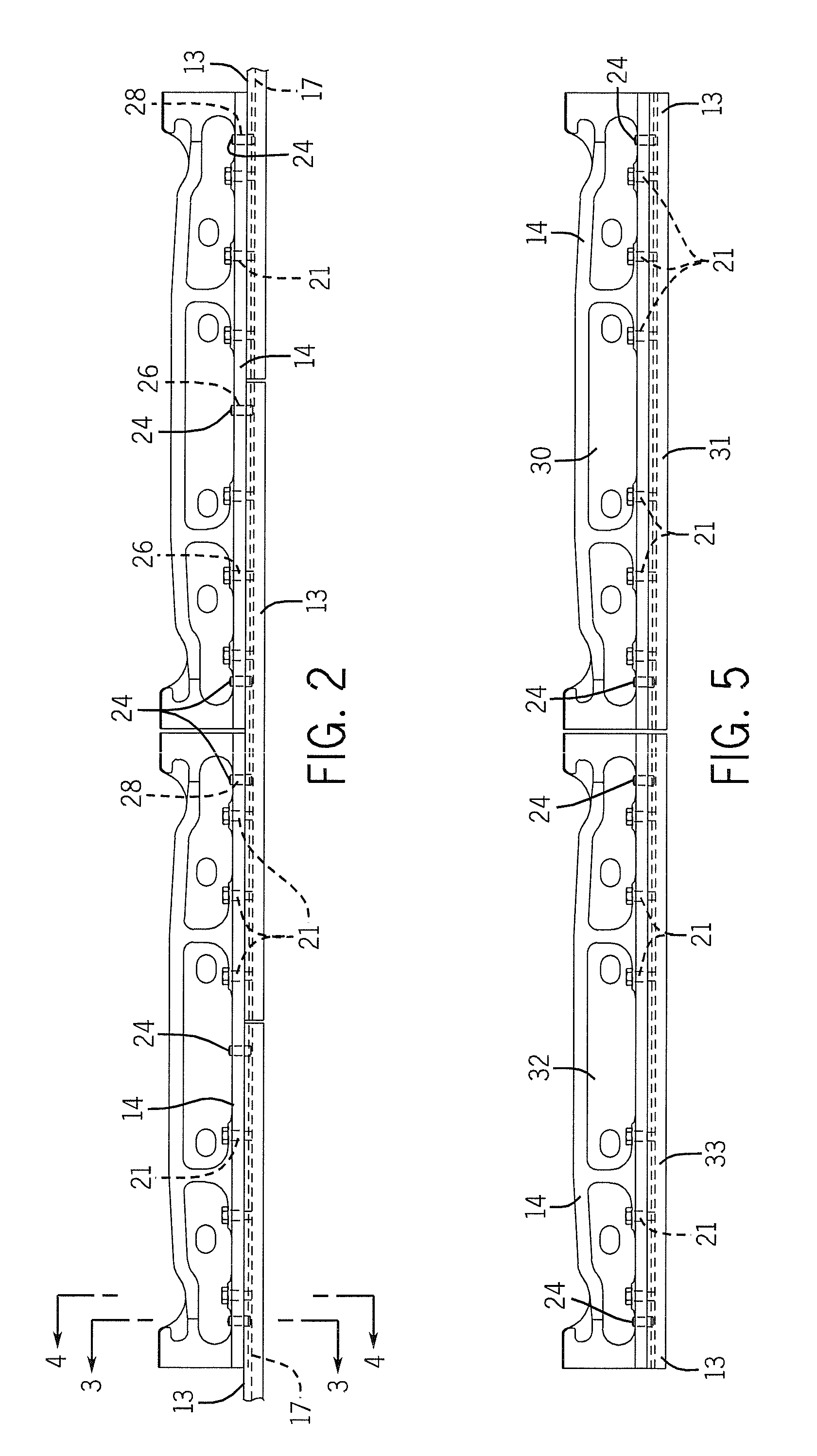
[0027]Referring also to FIG. 2, there is shown one of a pair of brake shoe assemblies 13 for one track 11 of a retarder. The partial assembly of FIG. 2 shows two adjacent brake beams 14 to which are attached three brake sho...


PUM


Abstract

Several embodiments of a system for connecting brake shoes to brake beams in a railroad car retarder all provide enhanced connecting joint tightness that reduces premature connecting joint loosening, reduces maintenance, and reduces failure of connecting bolts or equivalent connecting pins.

Description

CROSS REFERENCE TO RELATED APPLICATION[0001]This application relates to and claims priority from U.S. Provisional Application Ser. No. 61 / 166,101, filed on Apr. 2, 2009.BACKGROUND OF THE INVENTION[0002]The present invention pertains to rail car retarders used in railroad classification yards and, more particularly, to improved arrangements for attaching the brake shoes to the brake beams in a pneumatic retarder.[0003]Railroad car retarders are used in classification yards to regulate the speed of freight cars being arranged to make up a train or to be temporarily side tracked. Many types of hydraulic, pneumatic and mechanical systems are used to operate retarders. They all typically operate by clamping the railroad car wheels between a pair of parallel brake shoes positioned on each side of both track rails where they can be moved toward one another to clamp therebetween the wheels of a rolling freight car entering the retarder. The brake shoes are typically spring-biased or moved b...

Claims


Application Information

Patent Timeline
Patent Type & Authority Applications(United States)
IPC IPC(8): B61K7/02B61H13/36
CPCB61K7/02
Inventor HEYDEN, THOMAS J.
Owner AAA SALES ENG
Why Eureka
Try Eureka