Phase-Locked Loop (PLL) Having Extended Tracking Range

Inactive Publication Date: 2010-10-07
AVAGO TECH INT SALES PTE LTD
View PDF12 Cites 12 Cited by
  • Summary
  • Abstract
  • Description
  • Claims
  • Application Information

AI Technical Summary

Benefits of technology

[0006]The present invention meets the above-noted need by providing, in illustrative embodiments thereof, techniques for extending the tracking range of a PLL. Moreover, techniques of the invention provide the ability to extend the frequency tracking range of the PLL without modifying any core hardware of the PLL. Consequently, using techniques of illustrative embodiments of the present invention, a crystal oscillator having a larger frequency offset tolerance, in comparison to higher cost TCXOs, can be utilized, thereby resulting in a significant cost savings.

Problems solved by technology

Generally, the larger the tracking range of the PLL, the worse is the performance of the PLL.
However, a narrow tracking range does not allow the PLL to maintain synchronization with the incoming signal over fluctuations in the frequency of the incoming signal, in addition to variations in operating conditions and / or manufacturing characteristics to which the PLL may be subjected, such as, for example, process, voltage supply and / or temperature (PVT).
While it would be desirable to utilize a lower cost crystal in order to reduce the overall cost of the SDARS receiver, the frequency offset variation of the lower cost crystal is too large to satisfy the stringent frequency tracking requirements of many applications, such as SDARS.

Method used


Image

  • Phase-Locked Loop (PLL) Having Extended Tracking Range
  • Phase-Locked Loop (PLL) Having Extended Tracking Range
  • Phase-Locked Loop (PLL) Having Extended Tracking Range

Examples


Embodiment Construction

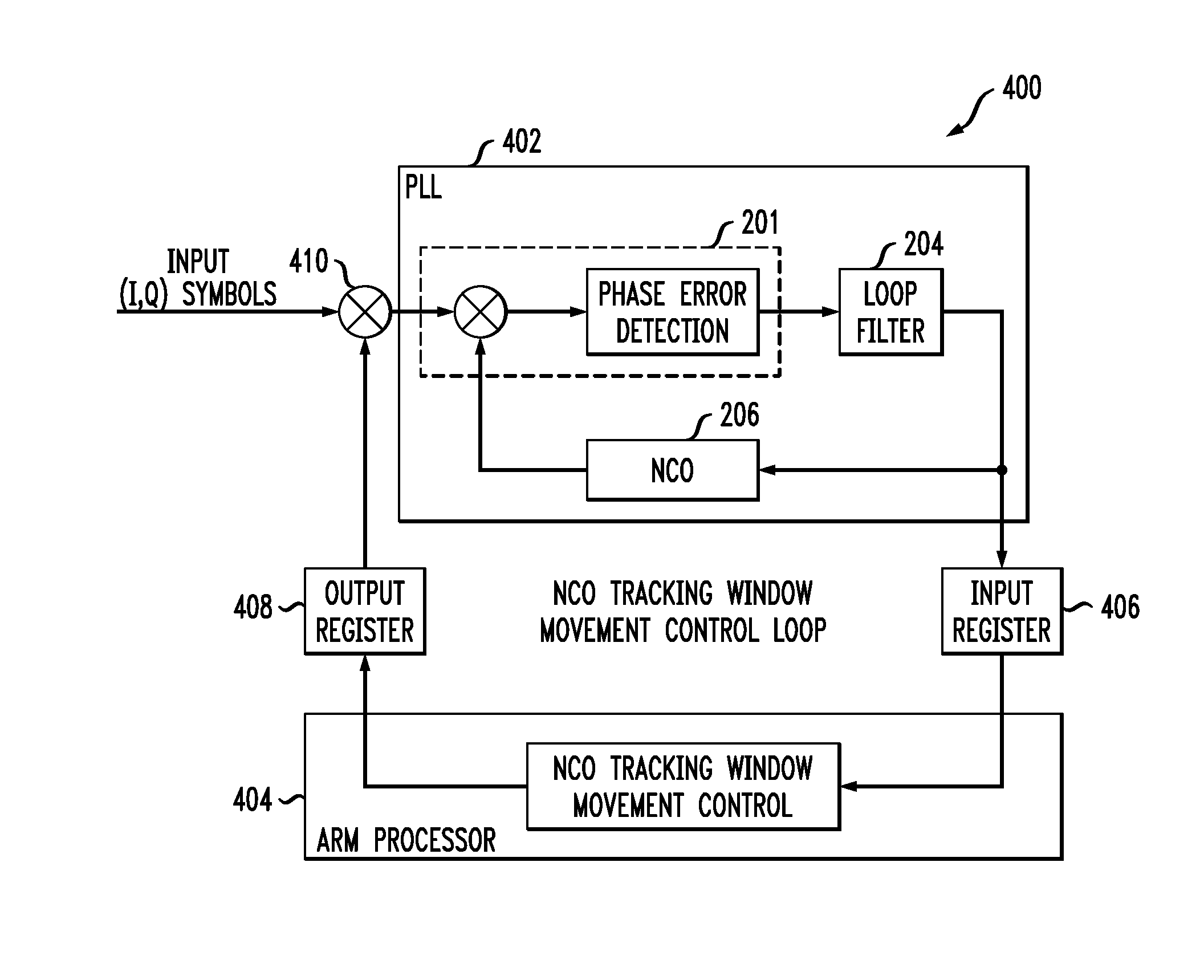
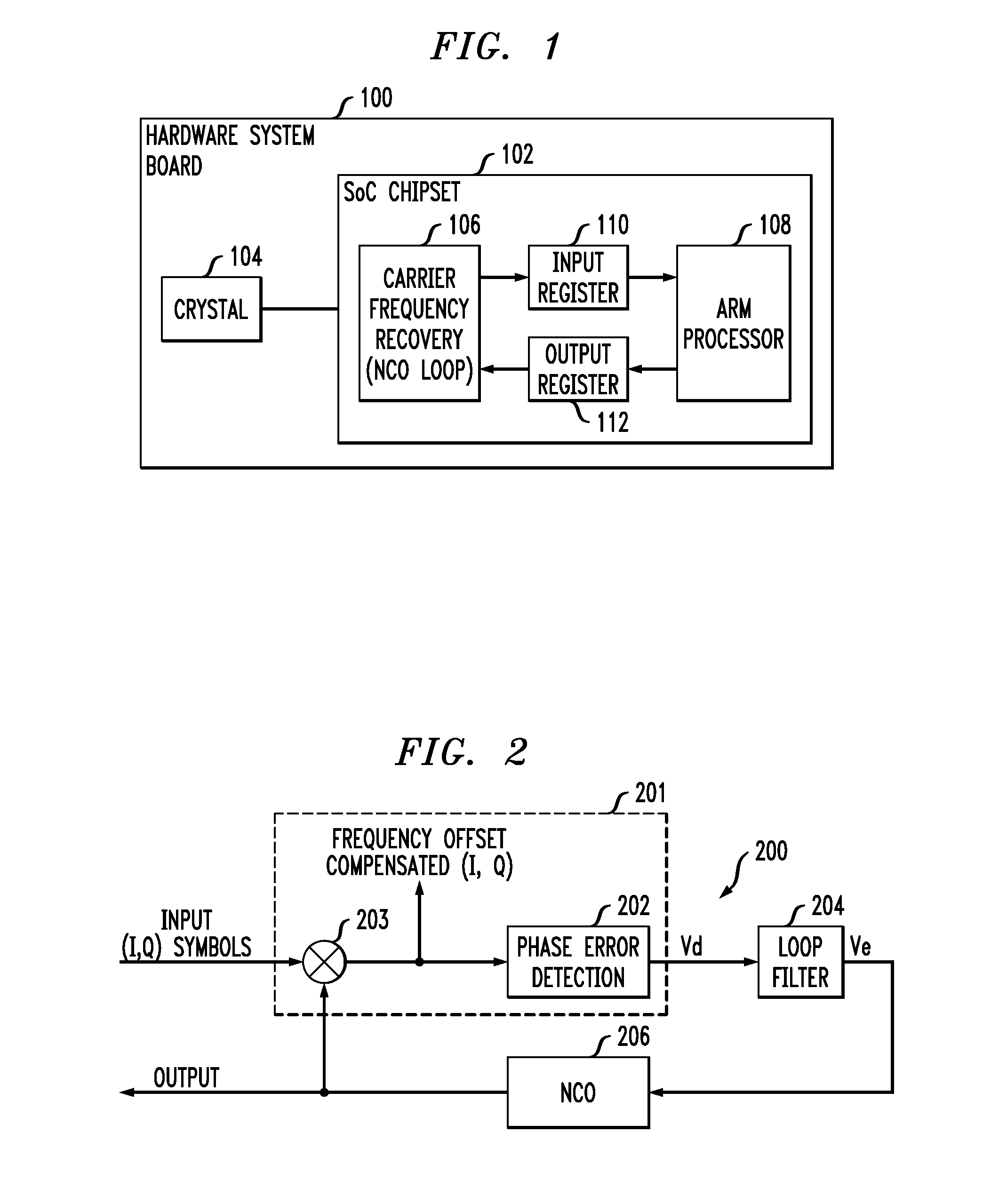
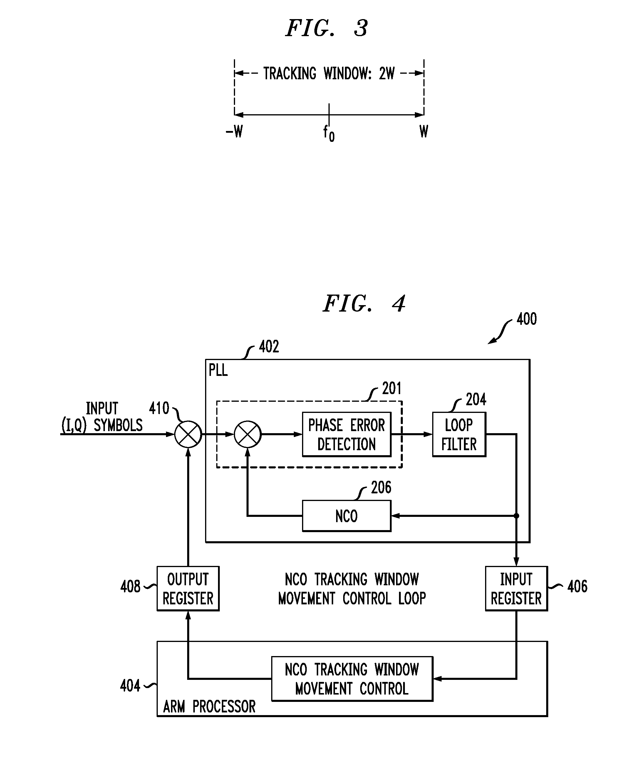
[0020]The present invention will be described herein in the context of an illustrative PLL circuit. It should be understood, however, that the present invention is not limited to this or any other particular circuit arrangements. Rather, the invention is more generally applicable to techniques for beneficially extending a tracking range of a PLL, in at least one aspect, by dynamically controlling a center frequency of a tracking window corresponding to the PLL so as to maintain lock with an incoming signal to the PLL over a wider frequency range. A width of the PLL tracking window is generally fixed and is optimally narrower for obtaining performance benefits. Techniques of the invention allow the PLL to beneficially retain the advantages of a narrower tracking window while being able to maintain signal lock over a wider range of frequencies of the input signal. Embodiments of the present invention advantageously facilitate compensation of the PLL for post-production variations, inc...


PUM


Abstract

A method for extending a tracking range of a PLL includes the steps of: establishing an initial tracking window of the PLL, the tracking window having a first width associated therewith; and dynamically adjusting the tracking window of the PLL within an extended tracking range when a frequency of an input signal supplied to the PLL is outside of the tracking window, the extended tracking range having a second width associated therewith which is greater than the first width.

Description

FIELD OF THE INVENTION[0001]The present invention relates generally to electronic circuits, and more particularly relates to techniques for enhancing the performance of a PLL.BACKGROUND OF THE INVENTION[0002]A PLL is a well-known frequency-selective feedback system which is adapted to generate a signal which can synchronize with a reference input signal and closely track the frequency changes which may be associated with the input signal. PLLs are utilized in numerous applications, including communication, telemetry and data-recovery applications.[0003]The range of frequencies over which the PLL can maintain synchronization with an input signal is typically defined as the tracking range, or lock range, of the system. This is different from the range of frequencies over which the PLL can first synchronize with the incoming signal, the latter range of frequencies being typically known as the capture range, or acquisition range, of the PLL. The capture range is characteristically alway...

Claims


Application Information

Patent Timeline
IPC IPC(8): H03L7/08
CPCH03L7/0991H04L2027/0046H03L7/10H03L7/12H03L7/1075
Inventor LAI, YHEAN-SENSONG, JIEWANG, ZHENYUYU, JINGUO
Owner AVAGO TECH INT SALES PTE LTD
Why Eureka
Try Eureka