Method and systems for particle characteruzation using optical sensor output signal fluctuation
- Summary
- Abstract
- Description
- Claims
- Application Information
AI Technical Summary
Benefits of technology
Problems solved by technology
Method used
Image

Examples
Embodiment Construction
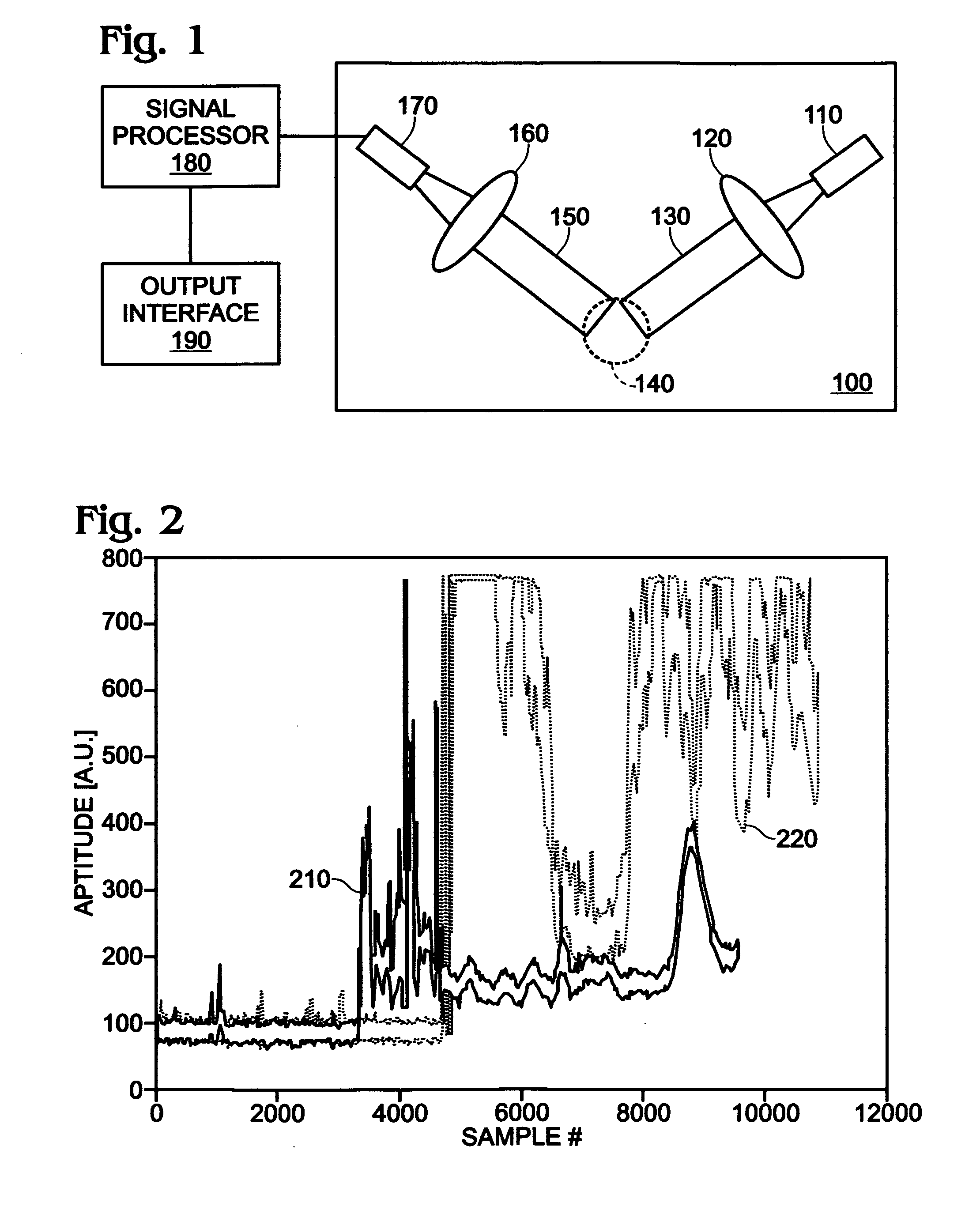
[0038]FIG. 1 shows an airborne particle detection and characterization system in some embodiments of the invention. The system may be integrated into a portable monitor worn by a patient, for example. The system includes a signal processor 180 communicatively coupled between an optical sensor 100 and an output interface 190. Optical sensor 100 has a light source 110, such as a light emitting diode (LED), that provides incident light to a first lens 120. First lens 120 collimates the incident light to produce collimated light 130. The collimated light 130 is scattered by particles in a light scattering region 140 to produce scattered light 150 that is indicative of particle presence in light scattering region 140. The scattered light 150 passes through a second lens 160 and is recorded by an optical detector 170 that converts the recorded light into a voltage. Optical detector 170 transmits to signal processor 180 an output signal that is proportional to the voltage. After performing...
PUM
 Abstract
Description
Claims
Application Information