

Photonic bandgap fiber
- Summary
- Abstract
- Description
- Claims
- Application Information
AI Technical Summary
Benefits of technology
Problems solved by technology
Method used
Image

Examples
examples
[0053]Hereunder is a description of an example of the present invention. However, it is obvious that the present invention is not limited to the following example.
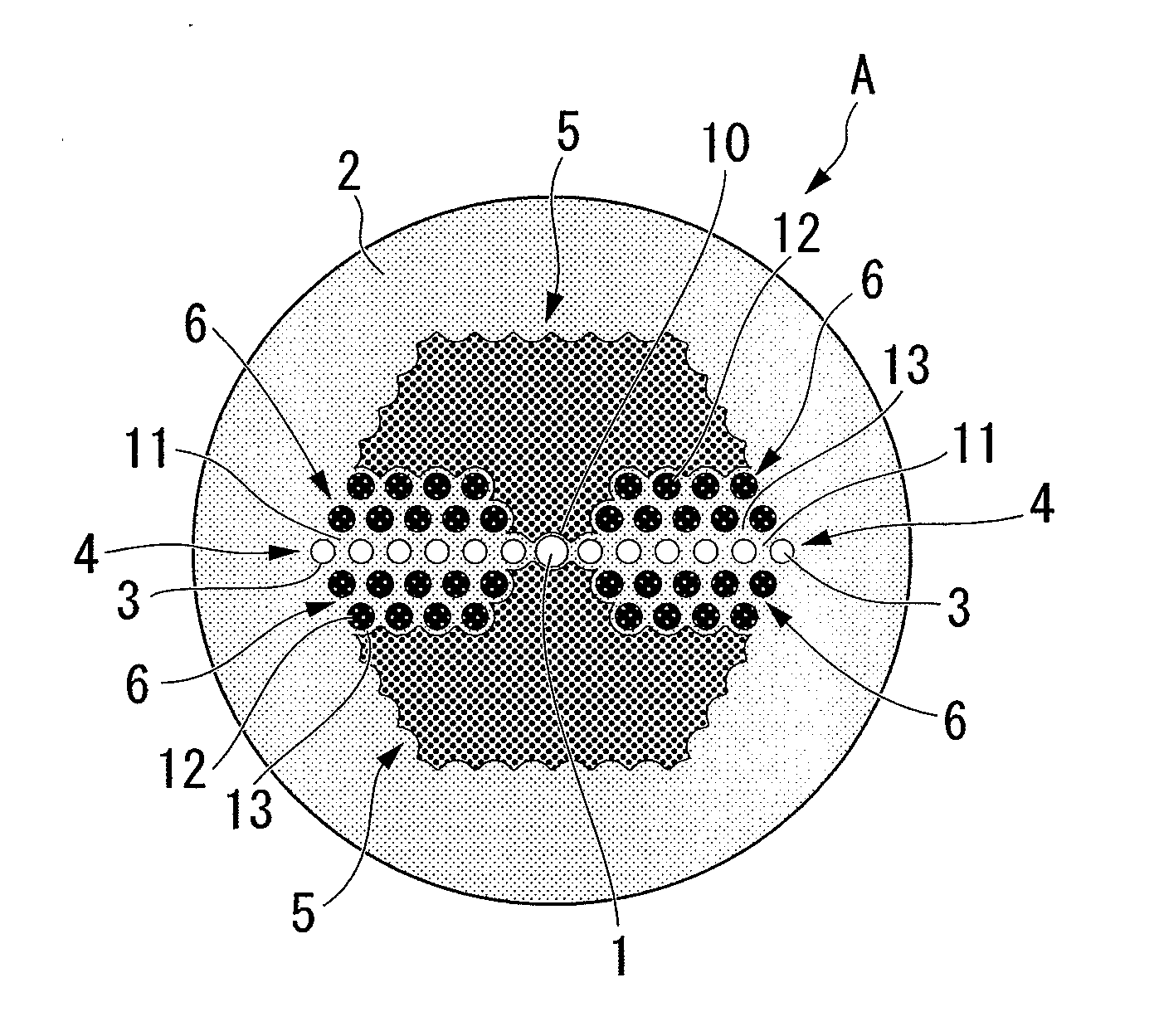
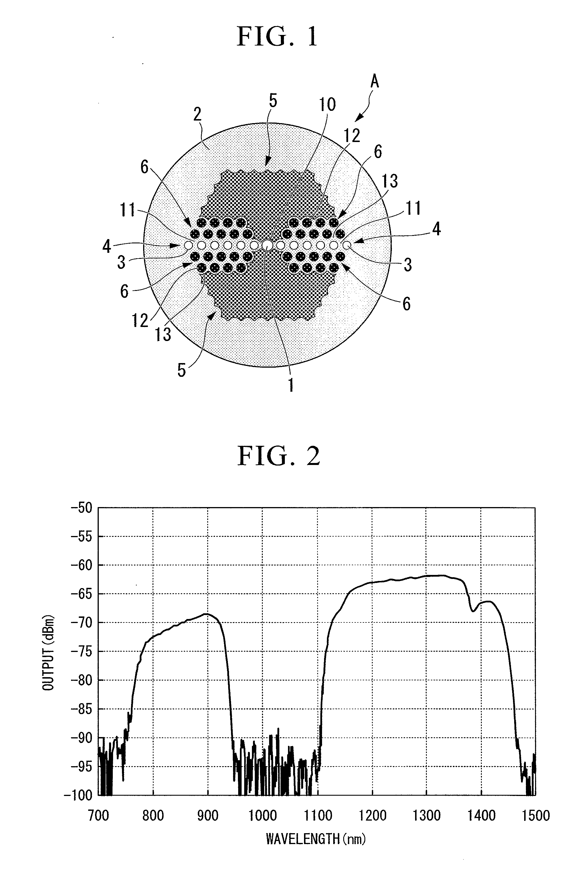
[0054]A photonic bandgap fiber with a structure shown in FIG. 1 was fabricated. In the fabricated structure, a core made from pure silica with a diameter d of 7.3 μm was surrounded by a cladding made from pure silica. Around the core, there were formed: a region in which high refractive index parts with a diameter dh of 4 μm are aligned with a period of 7.3 μm, the high refractive index parts having a relative refractive index difference Δh of +2.8% from pure silica; a region in which low-refractive-index stress applying parts with a diameter dh of 5 μm are arranged in a triangular lattice structure, the stress applying parts having a relative refractive index difference Δh of −0.5% from pure silica; and a low refractive index region having a relative refractive index difference Δl of −0.35% from pure silica. It was config...
PUM
 Abstract
Description
Claims
Application Information