Exposure head, exposure head control method, and image forming apparatus

Inactive Publication Date: 2010-10-07
SEIKO EPSON CORP
View PDF4 Cites 5 Cited by
  • Summary
  • Abstract
  • Description
  • Claims
  • Application Information

AI Technical Summary

Benefits of technology

[0007]An advantage of some aspects of the invention is to provide a technique that enables favorable exposure operations to be executed by suppressing fluctuations in the light amounts of light-emitting elements caused by decay therein.First Aspect
[0009]An exposure head according to a second aspect of the invention is the exposure head according to the first aspect, where the exposure head includes multiple light-emitting elements, the multiple light-emitting elements being disposed across a distance that is longer in a first direction than in a second direction and being disposed symmetrically; and the multiple reference elements are disposed on the outer sides of corresponding light-emitting elements in the first direction, and are disposed symmetrically relative to the center of symmetry of the multiple light-emitting elements. According to these aspects of the invention, the reference elements and multiple light-emitting elements are advantageous in terms of being placed approximately at the same temperature, thus making it possible to find the degree of decay of the light-emitting elements with more accuracy. As a result, the exposure head can execute favorable exposure operations.Third Aspect
[0013]According to the invention (exposure head, control method for an exposure head, and image forming apparatus) configured in this manner, a latent image formation operation (exposure operation) is executed by forming an image of light from multiple light-emitting elements using an image formation optical system. The amount of light from the light-emitting elements applied to the latent image formation operation is influenced both by decay caused by repeated latent image formation operations, and by temperature. Accordingly, as described above, there have been situations where the degree of decay of a light-emitting element cannot be accurately found. In response to this, the invention obtains the degree of decay of a light-emitting element based on the light amounts of multiple reference elements and multiple light-emitting elements. The multiple reference elements are provided relative to the multiple light-emitting elements, and are under approximately the same temperature as the multiple light-emitting elements. Furthermore, the reference elements are extinguished during the latent image formation operations, and thus do not experience decay due to the latent image formation operations. In other words, by using the light amounts of the reference elements, which are under approximately the same temperature as the multiple light-emitting elements and do not experience decay, the invention enables the degree of decay of each of the multiple light-emitting elements to be found with accuracy while also suppressing the influence of temperature. Accordingly, controlling the light amounts of the light-emitting elements based on these decay rates makes it possible for the exposure head to suppress fluctuations in the light amounts of the light-emitting elements caused by decay and execute favorable exposures. Furthermore, using such an exposure head makes it possible for the image forming apparatus to form a favorable image.
[0014]Meanwhile, the control method for an exposure head can be configured in the following manner. That is, the control method for an exposure head can be configured so that the degree of decay of a light-emitting element is found based on the light amounts of a light-emitting element caused to emit light and multiple reference elements, and the light amounts of a light-emitting element caused to emit light and the multiple reference elements as stored in a storage unit. Using such a configuration makes it possible to accurately obtain the degree of decay of a light-emitting element while also suppressing the influence of temperature, even in the case where the temperature differs between when the light amounts stored in the storage unit were obtained and when the multiple light-emitting elements and multiple reference elements are caused to emit light.

Problems solved by technology

Meanwhile, it has been known for some time that light-emitting elements decay with repeated light emissions, and the amount of light emitted by the light-emitting elements drops as a result.
When such a drop in the light amount occurs, there is a risk that the exposure head can no longer execute favorable exposure operations.
However, the light amount of a light-emitting element also fluctuates due to changes in temperature.
As a result, there have been cases where the degree of decay found based on the pre- and post-shipping light amount measurements is affected by a change in temperature, making it difficult to accurately obtain the degree of decay.
In such a case, light amount fluctuation caused by decay cannot be properly controlled, leading to the possibility that favorable exposure operations cannot be executed.
Accordingly, as described above, there have been situations where the degree of decay of a light-emitting element cannot be accurately found.

Method used


Image

  • Exposure head, exposure head control method, and image forming apparatus
  • Exposure head, exposure head control method, and image forming apparatus
  • Exposure head, exposure head control method, and image forming apparatus

Examples


Embodiment Construction

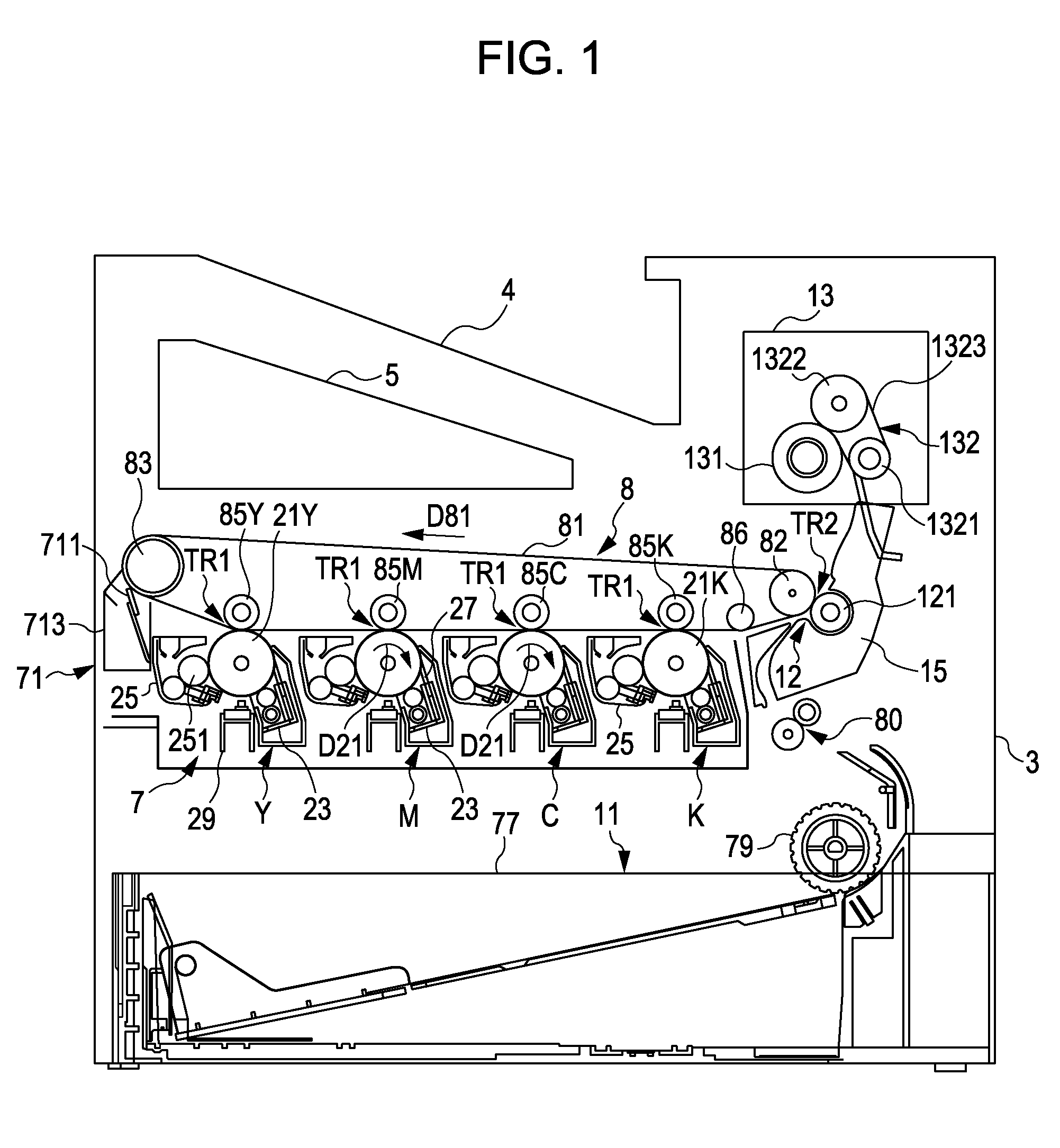
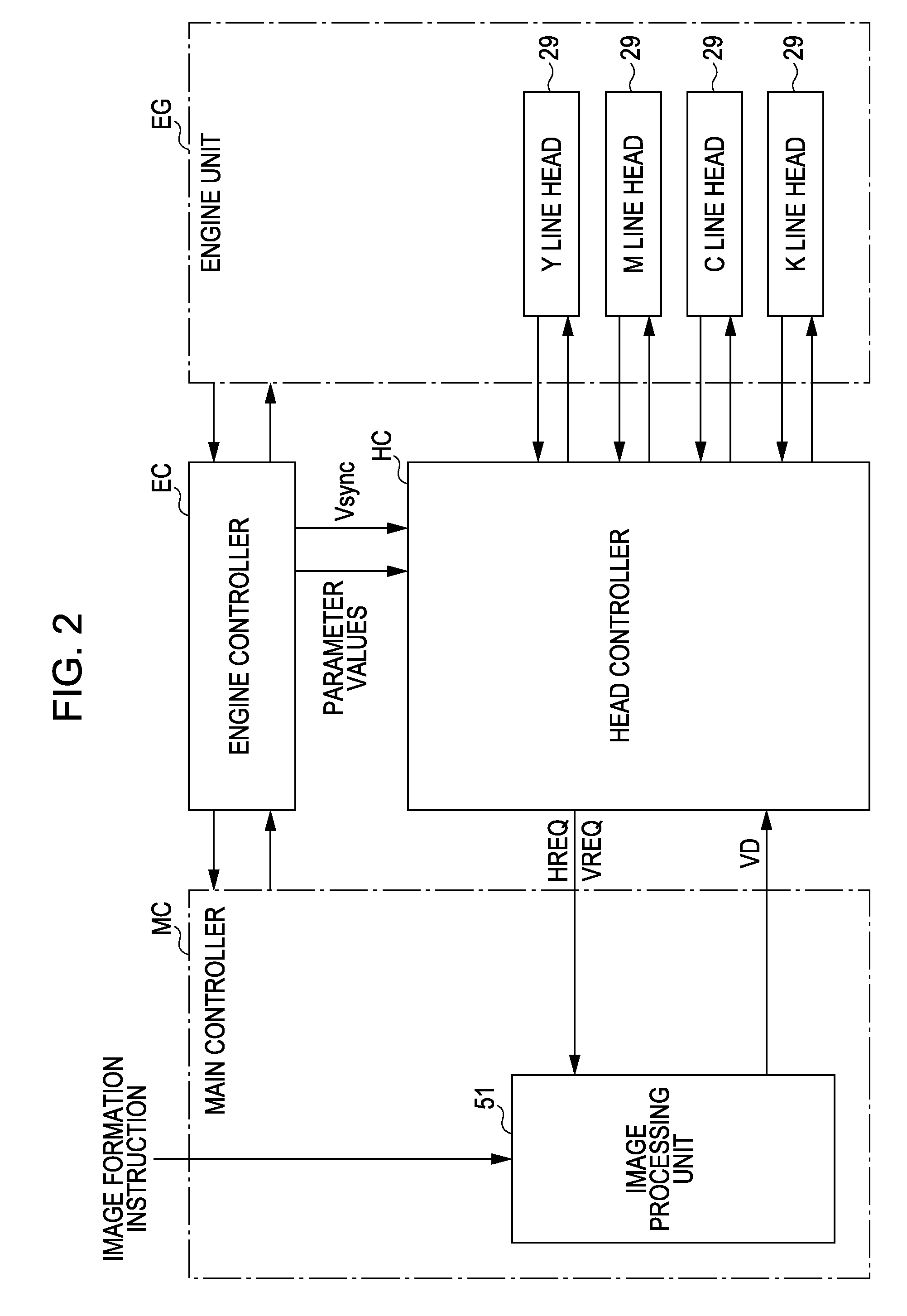
[0031]FIG. 1 is a schematic diagram illustrating an example of an image forming apparatus provided with a line head according to an embodiment of the invention. FIG. 2 is a block diagram illustrating the electrical configuration of the image forming apparatus illustrated in FIG. 1. This apparatus is an image forming apparatus capable of selectively executing a color mode, in which a color image is formed by superimposing four colors of toner, or black (K), cyan (C), magenta (M), and yellow (Y), or a monochromatic mode, in which a monochromatic image is formed using only black (K) toner. Note that FIG. 1 is a diagram illustrating the execution of the color mode.

[0032]As shown in FIG. 2, with this image forming apparatus, when a main controller MC including a CPU, a memory, and the like is provided with an image formation instruction from an external device such as a host computer, the main controller MC supplies a control signal to an engine controller EC and provides video data VD c...


PUM


Abstract

An exposure head includes: a light-emitting element; an image formation optical system that forms an image of light from the light-emitting element; multiple reference elements disposed relative to the light-emitting element; and a control unit that controls the light emission of the light-emitting element and extinguishes the reference elements during a latent image formation operation. The control unit finds the degree of decay of the light-emitting element based on the light amounts of the light-emitting element and the multiple reference elements at a time when the latent image formation operation is not being carried out, and controls the light amount of the light-emitting element during the latent image formation operation based on the degree of decay.

Description

BACKGROUND[0001]1. Technical Field[0002]The present invention relates to an exposure head that forms an image of light from a light-emitting element into an image using an image formation optical system, a control method for such an exposure head, and an image forming apparatus that employs such an exposure head.[0003]2. Related Art[0004]As an example of such an exposure head, JP-A-2008-36937 discloses an exposure head having a single image formation optical system relative to multiple light-emitting elements. The image formation optical system forms an image of light from the multiple light-emitting elements corresponding to the image formation optical system. An exposure target surface is then exposed with the light that has been formed into an image.[0005]Meanwhile, it has been known for some time that light-emitting elements decay with repeated light emissions, and the amount of light emitted by the light-emitting elements drops as a result. When such a drop in the light amount ...

Claims


Application Information

Patent Timeline
IPC IPC(8): G03G15/043
CPCB41J2/451G03G15/326G03G15/043G03G2215/0409G03G15/04072G03G15/55
Inventor TANAKA, HIROSHI
Owner SEIKO EPSON CORP
Why Eureka
Try Eureka