Exposure Head and an Image Forming Apparatus

Inactive Publication Date: 2009-07-23
SEIKO EPSON CORP
View PDF12 Cites 6 Cited by
  • Summary
  • Abstract
  • Description
  • Claims
  • Application Information

AI Technical Summary

Benefits of technology

[0007]An advantage of some aspects of the invention is to provide a technique which makes it possible to guide a large amount of light into lenses even at a high resolution and hence realize excellent exposure.
[0009]In the exposure head having such a structure, the first lens and the second lens are connected in the first direction. Hence, it is possible to make a large amount of light impinge upon the first and the second lenses without widening an interval between the first lens and the second lens in the first direction and to realize excellent exposure.
[0011]In the exposure head having this structure, the first lens and the second lens become connected in the first direction. It is therefore possible to make a large amount of light impinge upon the first lens and the second lens without widening an interval between the first lens and the second lens in the first direction and to realize excellent exposure.
[0013]In the image forming apparatus having this structure, the first lens and the second lens are connected in the first direction. It is therefore possible to make a large amount of light impinge upon the first lens and the second lens without widening an interval between the first lens and the second lens in the first direction and to realize excellent exposure.

Problems solved by technology

However, expansion of the diameter of the lenses which are arranged at predetermined intervals in the longitudinal direction (first direction) in the structure above increases the lens pitches in the longitudinal direction (first direction) and could result in a failure to attain a desired resolution.
In other words, the related techniques could sacrifice the resolution for increase of incident light in some instances.

Method used


Image

  • Exposure Head and an Image Forming Apparatus
  • Exposure Head and an Image Forming Apparatus
  • Exposure Head and an Image Forming Apparatus

Examples


first embodiment

B-1. First Embodiment

[0053]FIG. 3 is a diagram showing an embodiment of an image forming apparatus including a line head as an application subject of the invention. FIG. 4 is a diagram showing the electrical construction of the image forming apparatus of FIG. 3. This apparatus is an image forming apparatus that can selectively execute a color mode for forming a color image by superimposing four color toners of black (K), cyan (C), magenta (M) and yellow (Y) and a monochromatic mode for forming a monochromatic image using only black (K) toner. FIG. 3 is a diagram corresponding to the execution of the color mode. In this image forming apparatus, when an image formation command is given from an external apparatus such as a host computer to a main controller MC having a CPU and memories, the main controller MC feeds a control signal and the like to an engine controller EC and feeds video data VD corresponding to the image formation command to a head controller HC. This head controller H...

second embodiment

B-2. Second Embodiment

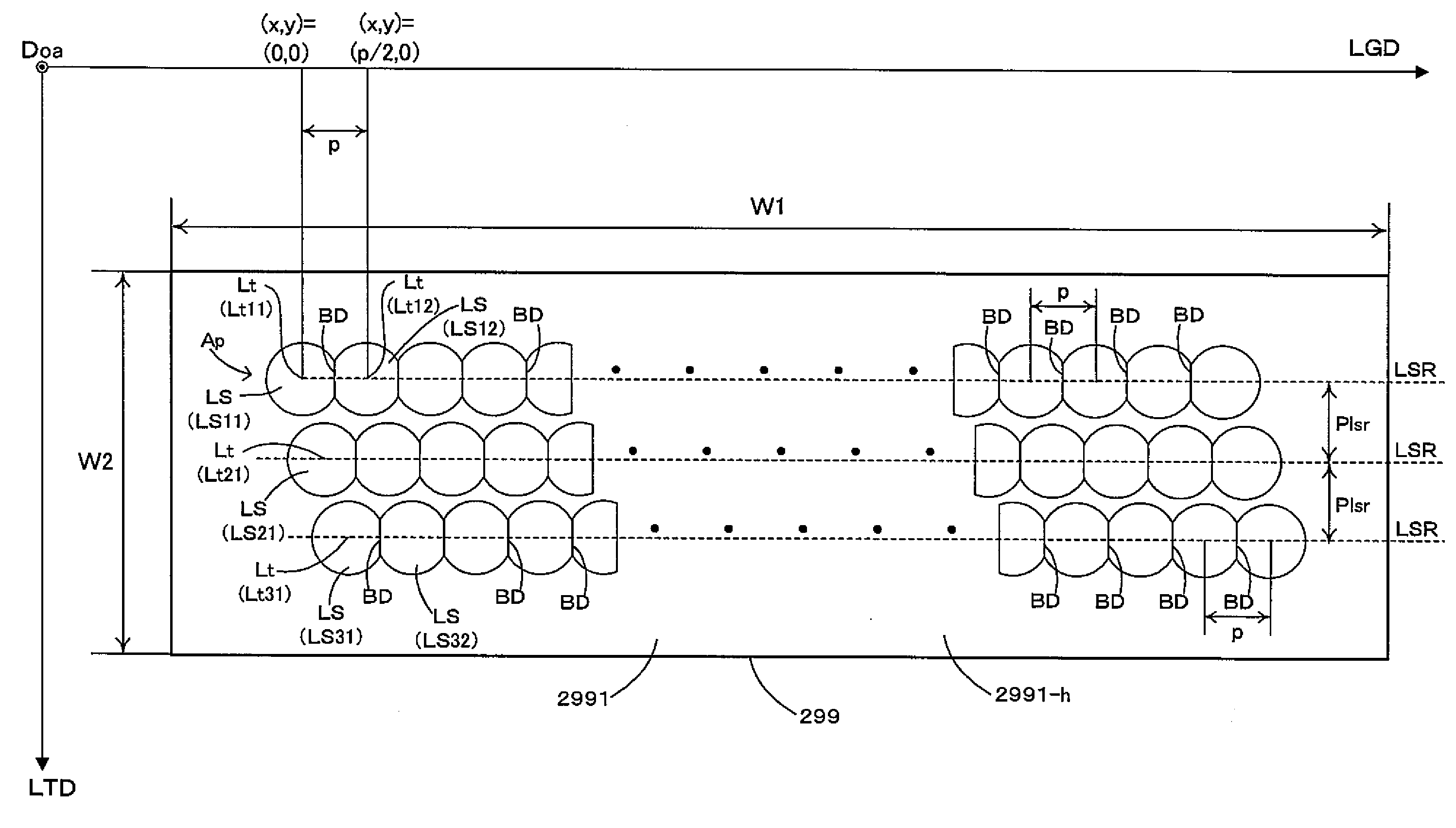
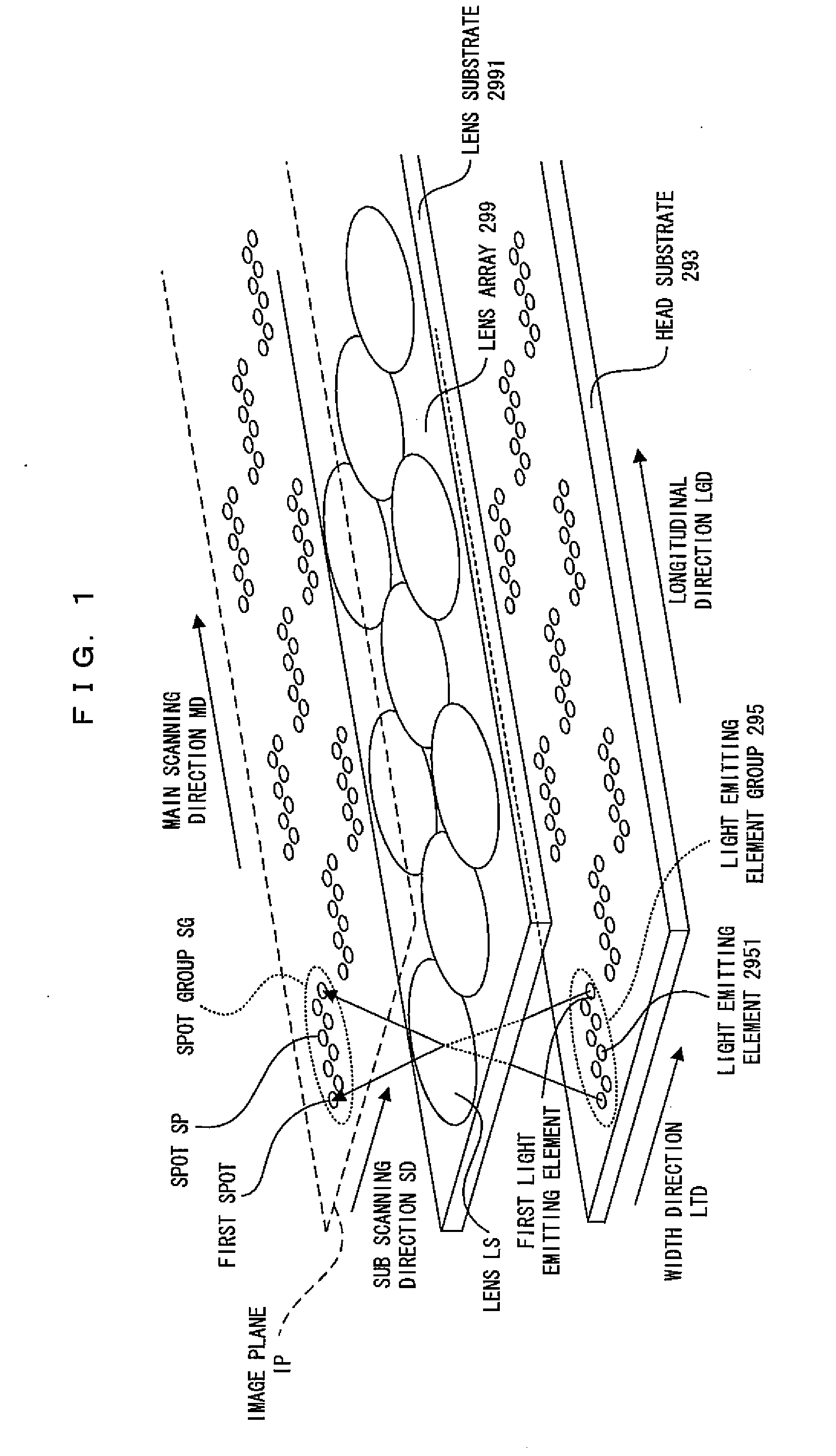
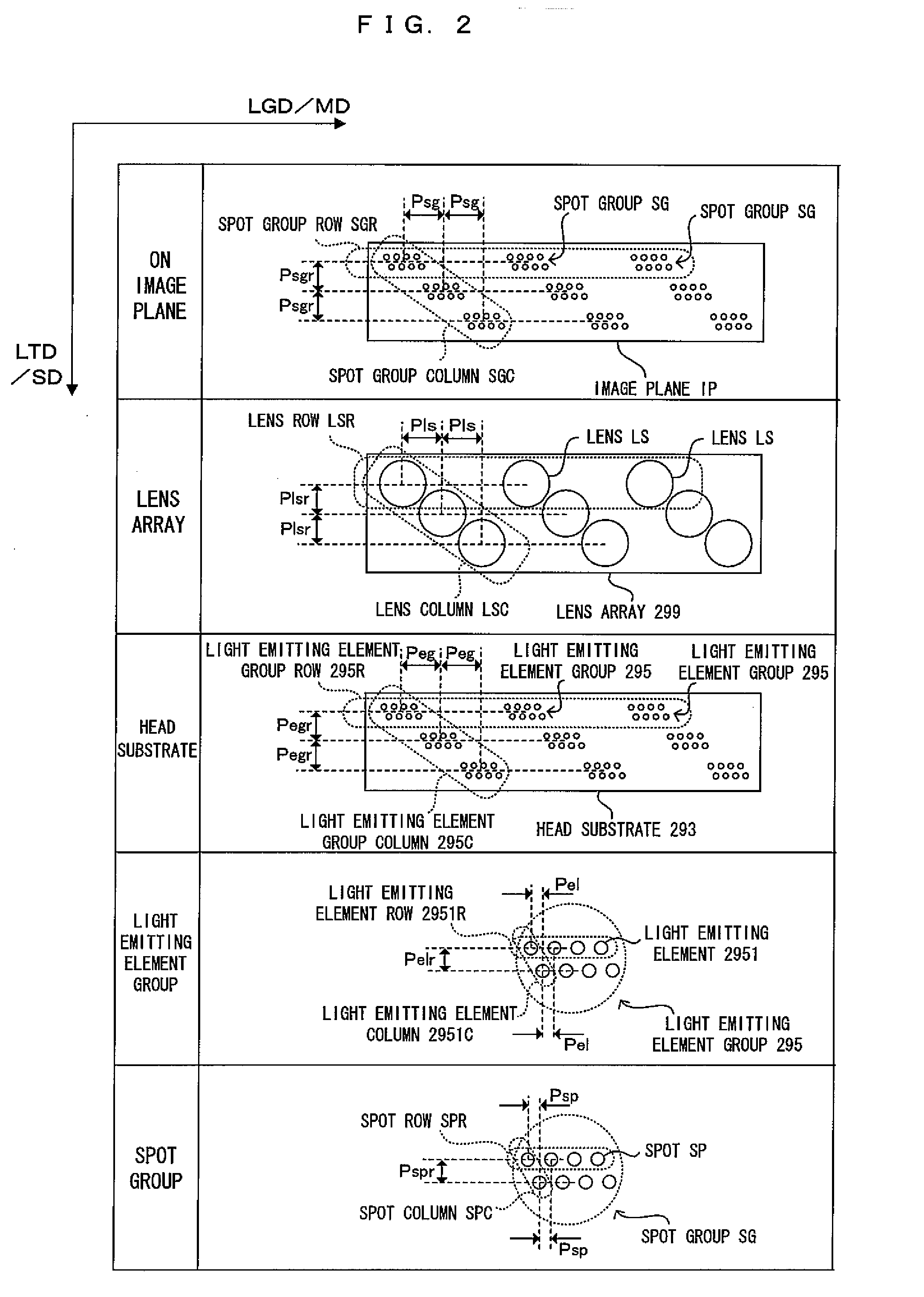
[0097]FIG. 13 is a schematic perspective view of a line head according to a second embodiment. FIG. 14 is a plan view of a lens array according to the second embodiment and corresponds to a case where the lens array is seen from the image plane side (that is, from the light beam propagation direction Doa). In FIG. 14, the respective lenses LS are provided on the under surface 2991-t of the lens array substrate 2991. The structure of the under surface 2991-t of the lens array substrate is shown in FIG. 14. In addition, while FIG. 14 shows light emitting element groups 295, this is merely to show how the light emitting element groups 295 correspond to the lenses LS without any intention to mean that the light emitting element groups 295 are provided on the under surface 2991-t of the lens array substrate. In the following, differences of the second embodiment from the first embodiment will be mainly described. Common aspects will be denoted at corresponding refer...

third embodiment

B-3. Third Embodiment

[0102]By the way, in the structure shown in FIG. 14, the lenses LS-u (a first lens and a second lens) are connected with the lenses LS-m (a third lens) so that it is possible for the lenses to receive a large amount of light without widening the gaps between the lenses LS-u and the lenses LS-m. Further, the lenses LS-m (a first lens and a second lens) are connected with the lenses LS-d (a third lens) so that it is possible for the lenses to receive a large amount of light without widening the gaps between the lenses LS-m and the lenses LS-d. In other words, the structure shown in FIG. 14 is capable of reducing the width of the lens array 299 in the width direction LTD (second direction). As a result, it is also possible to reduce in the width direction LTD the area on the head substrate 293 where the light emitting elements 2951 corresponding to the respective lenses LS are arranged. It is therefore possible to secure extra spaces at the both sides of the head s...


PUM


Abstract

An exposure head, includes: a lens array that includes a light transmissive substrate whose length in a first direction is greater than a length thereof in a second direction orthogonal to the first direction, a first lens that is arranged on the light transmissive substrate, and a second lens that is arranged on the light transmissive substrate at the first direction of the first lens, the first lens and the second lens being connected in the first direction; and a head substrate that is provided with a first light emitting element that emits a light toward the first lens and a second light emitting element that emits a light toward the second lens.

Description

CROSS REFERENCE TO RELATED APPLICATION[0001]The disclosure of Japanese Patent Applications No. 2008-008939 filed on Jan. 18, 2008 and No. 2008-306479 filed on Dec. 1, 2008 including specification, drawings and claims is incorporated herein by reference in its entirety.BACKGROUND[0002]1. Technical Field[0003]The invention relates to an exposure head and an image forming apparatus which use a lens array in which lenses are arranged.[0004]2. Related Art[0005]Known as such lens arrays include for example one in which lenses are arranged over predetermined pitches in a longitudinal direction as shown in FIG. 2 of JP-A-6-278314, etc. In this lens array, the lenses adjacent to each other in the longitudinal direction are at predetermined intervals from each other and each lens focuses incident light. Light focused by the respective lenses exposes a latent image carrier such as a photosensitive drum to form a latent image.SUMMARY[0006]By the way, a large amount of light impinging upon a len...

Claims


Application Information

Patent Timeline
IPC IPC(8): G02B27/16
CPCG02B3/0006B41J2/451
Inventor KOIZUMI, RYUTANOMURA, YUJIROSOWA, TAKESHI
Owner SEIKO EPSON CORP
Why Eureka
Try Eureka