Cooling Assembly Comprising Several Cooling Pins For Cooling Hollow Moulded Plastic Pieces By Means Of A Cooling Fluid Flow Boosted By Venturi Effect

Active Publication Date: 2010-10-07
PLASTIPAK BAWT S A R L
View PDF10 Cites 4 Cited by
  • Summary
  • Abstract
  • Description
  • Claims
  • Application Information

AI Technical Summary

Benefits of technology

[0010]One main and general objective of the invention is to propose a novel technical solution that generally improves

Problems solved by technology

The fluid distribution between this source of compressed cooling fluid and the different rows of cooling pins of one plate creates however a non uniform distribution of fluid pressure between the cooling pins.
This pressure unbalance between the cooling pins is detrimental for the quality of the cooling operation; in particular, the cooling

Method used


Image

  • Cooling Assembly Comprising Several Cooling Pins For Cooling Hollow Moulded Plastic Pieces By Means Of A Cooling Fluid Flow Boosted By Venturi Effect
  • Cooling Assembly Comprising Several Cooling Pins For Cooling Hollow Moulded Plastic Pieces By Means Of A Cooling Fluid Flow Boosted By Venturi Effect
  • Cooling Assembly Comprising Several Cooling Pins For Cooling Hollow Moulded Plastic Pieces By Means Of A Cooling Fluid Flow Boosted By Venturi Effect

Examples


Example

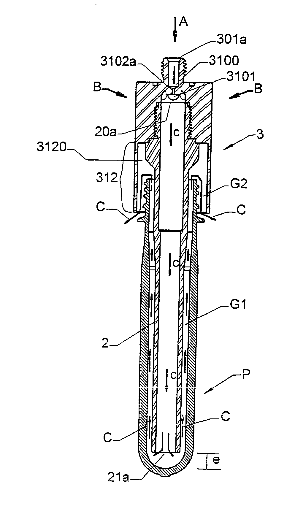
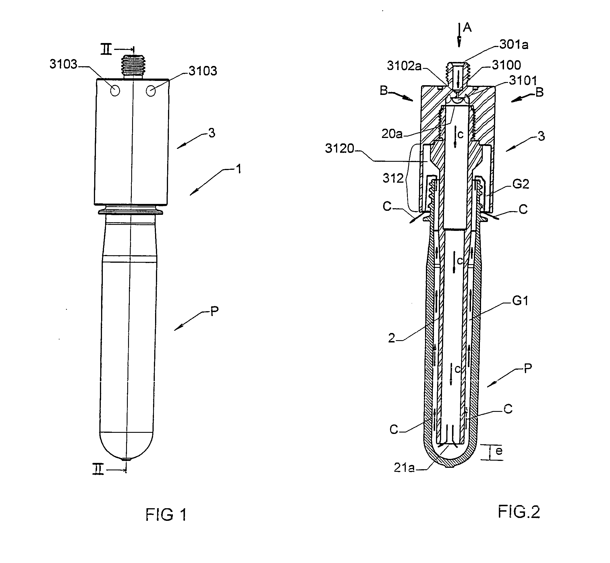
[0035]Referring to FIGS. 1 and 2, a cooling pin 1 of the invention is positioned on a plastic preform P that has been freshly moulded. In this preferred embodiment, the cooling pin 1 is made of two assembled metal pieces: a blowing pipe 2 and fluid boosting means 3 referred hereafter as booster 3.

[0036]Referring to FIGS. 8 and 9, the blowing pipe 2 is a rectilinear hollow tube that is opened at both ends 20 (proximal end) and 21 (distal end). The opening 20a in proximal end 20 constitutes an inlet for the cooling fluid, and the opposite opening 21a in the distal end 21 constitutes an outlet for the cooling fluid.

[0037]The blowing pipe 2 further comprises an external thread 22 for assembling the pipe 2 with booster 3.

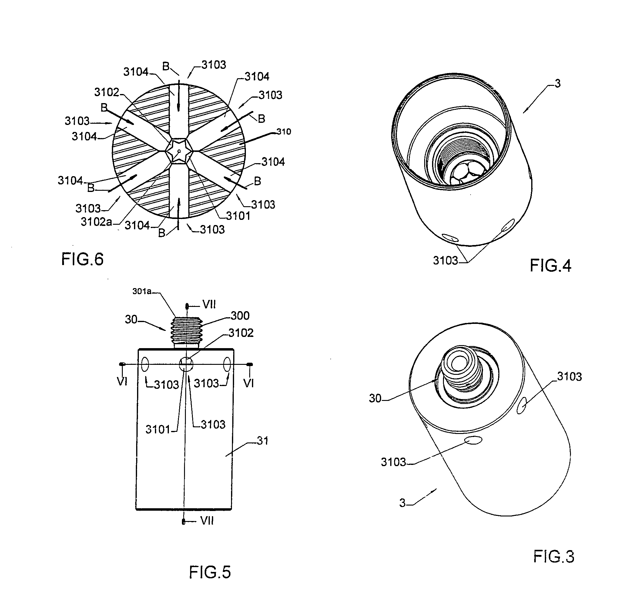
[0038]Referring to FIGS. 3 to 7, booster 3 is made of one single piece comprising a first cylindrical connecting part 30 of small diameter and a second cylindrical part 31 of higher diameter.

[0039]The first cylindrical connecting part 30 is used for quickly assembling th...


PUM

PropertyMeasurementUnit
Fractionaaaaaaaaaa
Fractionaaaaaaaaaa
Pressureaaaaaaaaaa

Abstract

The cooling assembly comprising several cooling pins (1) that are connected to the same fluid inlet. Each cooling pin (1) is adapted to cool a moulded hollow plastic piece (P), and comprises a hollow blowing pipe (2) having a fluid inlet (20a) at one end and at least one fluid outlet (21a) at the opposite end, and fluid boosting means (3) for boosting by Venturi effect the cooling fluid flow at the inlet (20a) of the blowing pipe (2). The cooling assembly can be mounted on a moulding machine, and in particular an injection moulding machine.

Description

FIELD OF THE INVENTION [0001]The present invention relates to the cooling of hollow moulded plastic pieces after the moulding operation is finished. The invention is more particularly useful in the field of injection blow moulding for post mould cooling a plastic piece before ejection of the said moulded piece from the injection mould. Preferably, the hollow moulded pieces are plastic preforms. In this technical field, the invention mainly relates to an improved cooling pin comprising a hollow pipe that can be introduced inside the hollow plastic piece and that is used for introducing a cooling fluid inside the plastic piece.PRIOR ART [0002]A variety of post mould cooling methods are currently used on injection moulding machines in order to obtain a rapid and efficient cooling of freshly moulded plastic hollow pieces, such as for example plastic preforms. In particular, in the field of injection stretch-blow moulding, the cooling of the preforms, after the moulding operation is fini...

Claims


Application Information

Patent Timeline
IPC IPC(8): B29C35/16F25D31/00F25D25/00
CPCB29C45/7207B29C49/04B29C49/06B29C49/6427B29K2105/253B29C2035/1683B29C2049/6623B29K2067/00B29C2035/1666B29C49/64B29C2949/0715B29C49/643
Inventor DECKERS, JANDUCHATEAU, ROALD
Owner PLASTIPAK BAWT S A R L
Why Eureka
Try Eureka