Extended short span tee for drywall ceiling

a drywall ceiling and short-span technology, applied in the field of short-span flat drywall ceiling construction, can solve the problems of increasing construction costs, incurred, and equipment frequently interferes with the installation of suspension wires, and achieves cost savings, increased section modulus, and effective rigidity.

Inactive Publication Date: 2010-10-14
USG INTERIORS INC
View PDF39 Cites 20 Cited by
  • Summary
  • Abstract
  • Description
  • Claims
  • Application Information

AI Technical Summary

Benefits of technology

[0003]The invention involves an improved tee construction that can advantageously be used for supporting flat drywall ceilings in extended “short span” applications. The disclosed tee construction is capable of supporting standard drywall sheets and satisfying applicable building codes while avoiding the need for suspension wires. The tees of the invention are sufficiently rigid to enable them to be supported exclusively at their ends on conventional wall angles. This rigidity avoids the labor of anchoring overhead suspension wires and the problems associated with interference with equipment in the space above the ceiling. The disclosed tees are commercially made with mostly existing technology, tooling, and material stock. Only a limited quantity of extra material is used in the manufacture of the disclosed tee forms of the invention.
[0004]More specifically, standard drywall tees are effectively rigidified by increasing their section modulus with a channel sized to closely fit with the standard reinforcing bulb provided at the top of the inverted standard drywall tee form. The resulting tee, in accordance with the invention, is familiar in form and size. The relatively low profile or height of the inventive tee affords full utilization of the space above the ceiling for free placement of utilities, duct work and like equipment without the need to leave clearance for suspension wires or to improvise and fabricate custom anchor points for the suspension wires. The freedom to use the full space of the plenum and not be hindered by suspension wires or supplemental brackets or supports is an important feature. This freedom is in addition to the basic cost savings obtained by eliminating the need for locating, installing, and tying off suspension wires.
[0005]The disclosed tee construction of the invention retains the benefit of a relatively light gauge tee body material and a single wall flange thereby affording easy and reliable penetration by self-drilling drywall screws.

Problems solved by technology

The presence of this and like equipment frequently interferes with the installation of suspension wires.
As a result, additional layout planning, tradesmen scheduling and, eventually, more labor, is incurred.
Frequently, unforeseen physical interference problems add to the cost of construction.

Method used


Image

  • Extended short span tee for drywall ceiling
  • Extended short span tee for drywall ceiling
  • Extended short span tee for drywall ceiling

Examples


first embodiment

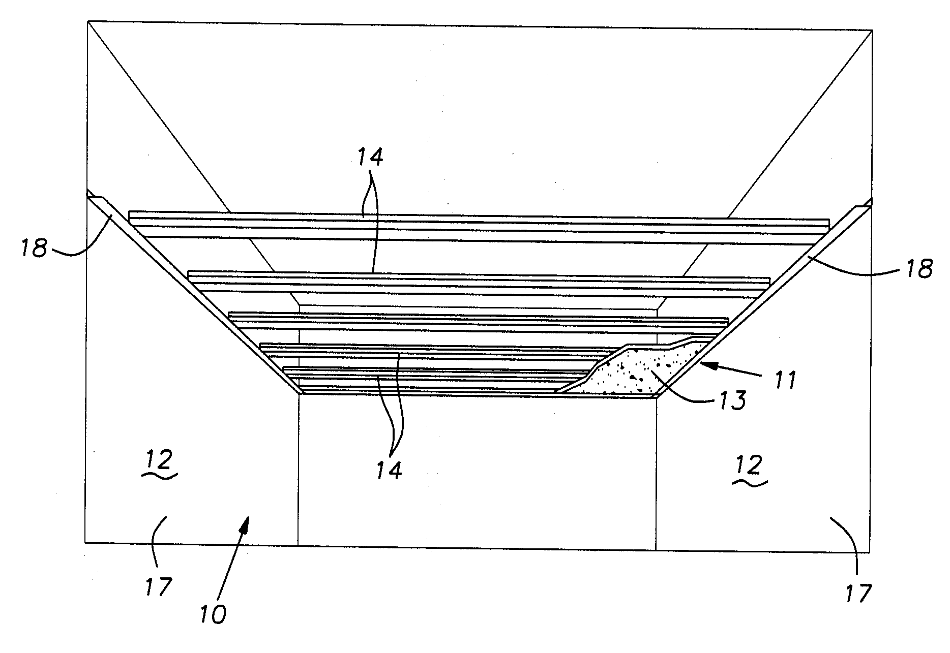
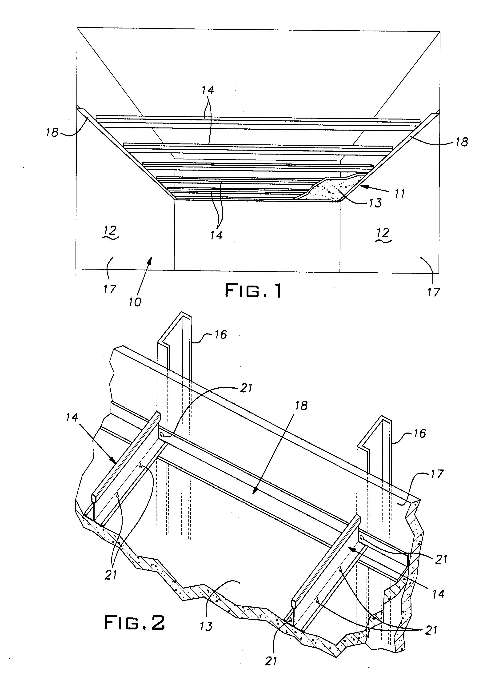
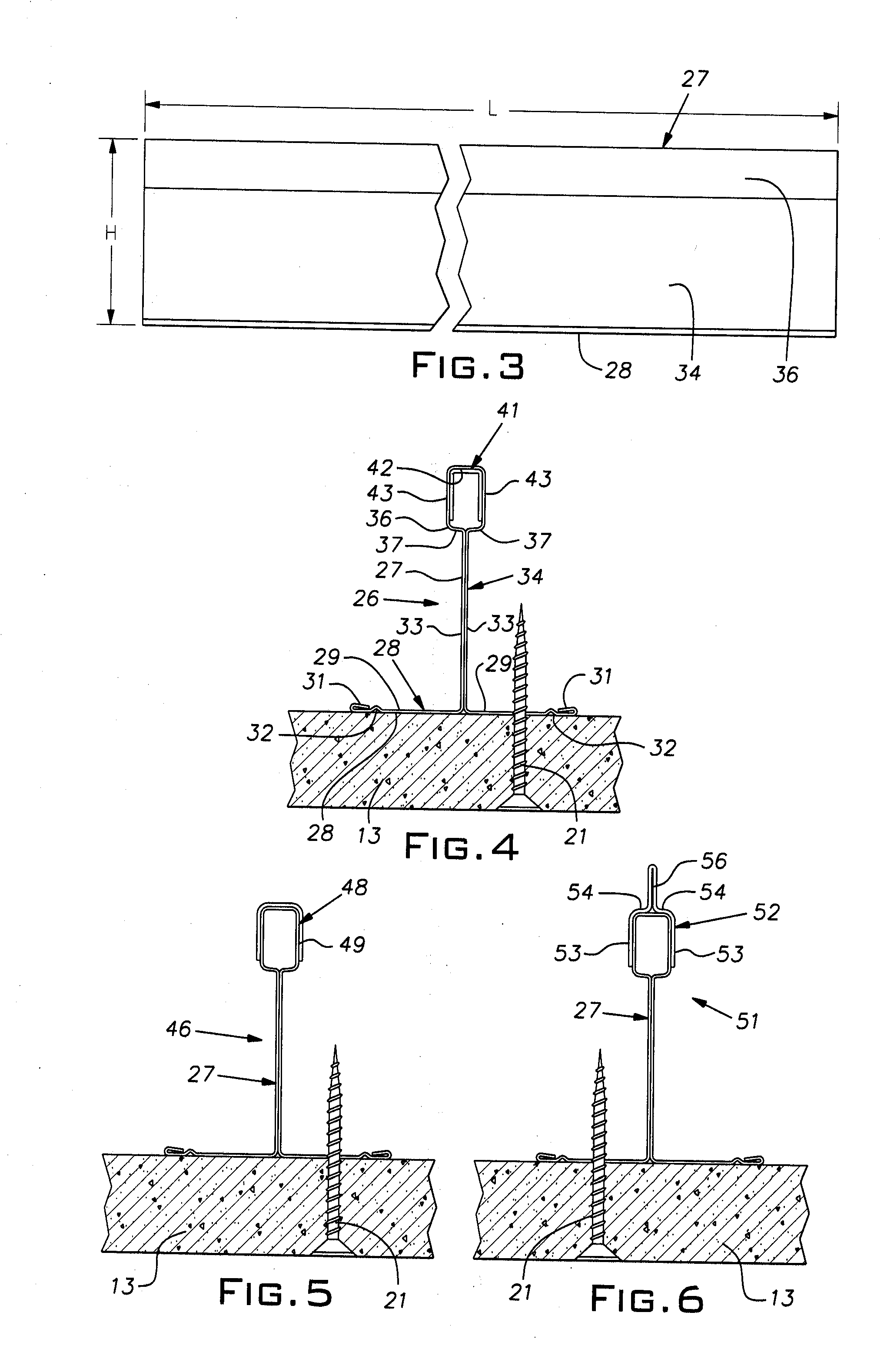
[0015]FIG. 4 illustrates a tee 26 in cross-section. The tee has a main body 27 roll-formed of a single strip of sheet metal. The strip is, for example, relatively light gauge stock being about 0.018″ galvanized (G40) hot-dipped steel (HDG). The form of the tee main body 27 is conventional. At the lower side, the tee main body 27 includes a single layer horizontal flange 28 comprising oppositely extending parts 29. Distal edges of the flange parts 29 have hems 31 folded over their upper sides. Adjacent and parallel to their distal edges, the flange parts 29 have small grooves 32 that serve to restrain screws from “skating” laterally off of the lower face of the flange 28 when being screwed into the flange. Additionally, the lower face of the flange 28 can be knurled, as is known, to stabilize a screw tip and further prevent it from skating across this lower flange face. At their proximal edges, the flange parts 29 merge integrally with respective layers 33 of a double layer or double...

second embodiment

[0019]FIG. 5 illustrates a tee 46 in cross-section. A tee main body can be identical to the tee main body 27 disclosed in connection with FIGS. 1-4. In the tee 46 of FIG. 5, an inverted channel 48 is fitted, cap-like, over the reinforcing bulb 36. Channel 48 is preferably roll-formed from a strip of sheet steel of a gauge somewhat heavier than the gauge of the main tee body 27. The channel gauge can be nominally a minimum of 0.024″, for example. The channel 48 includes a pair of sides 49 proportioned to closely abut the sides of the hollow reinforcing bulb 36 and to extend vertically over a major portion of the vertical height of the bulb. The channel 48 is rigidly fixed in place on the main body by appropriate staking, piercing, riveting, welding, or the like. The length of the channel 48 need not extend the full length of the main tee body 27 and can, for example, be half or more in length as the length of the tee main body and be centered lengthwise over the tee main body.

[0020]F...


PUM


Abstract

A short span flat drywall ceiling construction comprising a pair of spaced parallel wall angles facing one another, the wall angles each having a vertical leg secured to vertical support surfaces and a horizontal leg cantilevered from its respective vertical leg towards the other wall angle, a plurality of substantially identical roll-formed sheet metal tees extending between the wall angles and vertically supported thereby, each tee having a main body formed of a single strip of sheet steel, the tee having a horizontal single layer lower flange, a vertical double layer central web disposed above the flange, and a bulb at the top of the web centered on a plane of symmetry, a sheet metal U-shaped reinforcement channel fitted on a central part of the length of the tee such that it is in contact with at least the sidewalls of the bulb.

Description

BACKGROUND OF THE INVENTION[0001]The invention relates to building construction and, in particular, to short span flat drywall ceiling construction.PRIOR ART[0002]A type of ceiling construction found in commercial buildings involves the use of horizontally spaced inverted metal tees suspended by wires from overlying structure. Sheets of drywall are fastened by screws to these metal tees and then are taped and otherwise finished. Building areas such as corridors, stairwells, landings, and small rooms found in apartments, condominiums, hotels, motels, dormitories, and the like are commonly finished with flat drywall ceilings. These building areas are typically relatively narrow and, therefore, involve a relatively short span from wall-to-wall. In many instances, the space or plenum above the ceiling, especially in corridors and hallways, is occupied by duct work, conduit, and mechanical equipment. The presence of this and like equipment frequently interferes with the installation of s...

Claims


Application Information

Patent Timeline
Patent Type & Authority Applications(United States)
IPC IPC(8): E04B9/22
CPCE04B9/245E04B9/068
Inventor RAHEEL, MUHAMMADGULBRANDSEN, PEDERLEHANE, JAMES J.
Owner USG INTERIORS INC
Why Eureka
Try Eureka