Module for a Modular Conveyor Belt

a conveyor belt and modular technology, applied in metal-working equipment, packaging, metal-working equipment, etc., can solve the problems of plastic deformation, structural failure, and easy stress on the retainer,

Active Publication Date: 2010-10-14
LAITRAM LLC
View PDF33 Cites 8 Cited by
  • Summary
  • Abstract
  • Description
  • Claims
  • Application Information

AI Technical Summary

Benefits of technology

[0005]This invention provides a module for a modular conveyor belt which can prevent a hinge

Problems solved by technology

This method of bending the retainer may not cause a problem if the prying force is exerted near the free end of the retainer, but if the prying force is applied near the fixed end or near the midportion of the retainer, the retainer can easily be subjected to stresses which exceed its design stress.
As

Method used


Image

  • Module for a Modular Conveyor Belt
  • Module for a Modular Conveyor Belt
  • Module for a Modular Conveyor Belt

Examples


Embodiment Construction

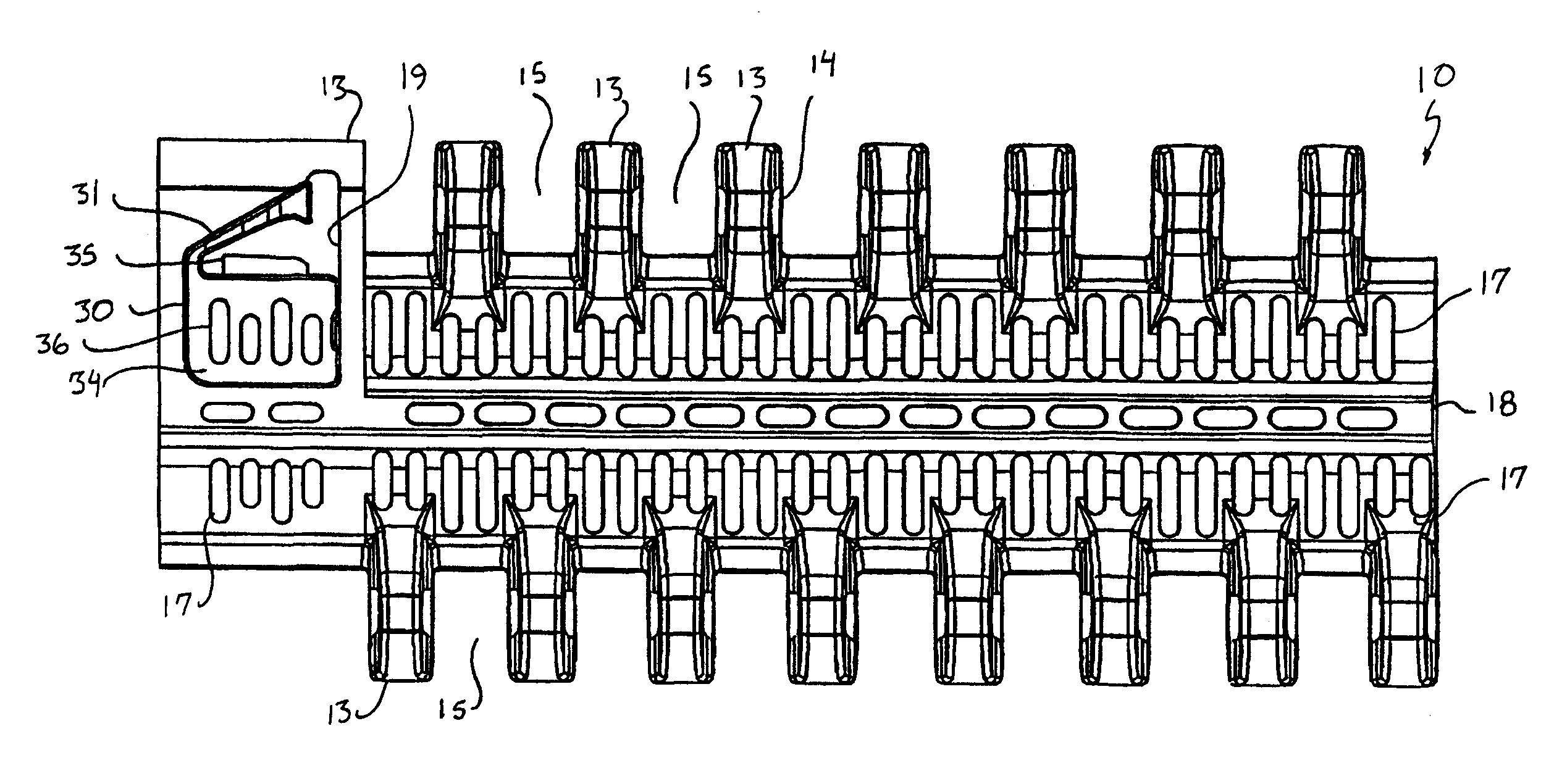
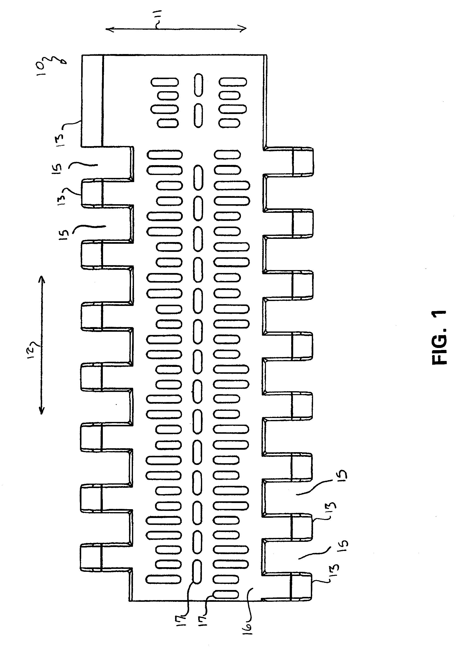
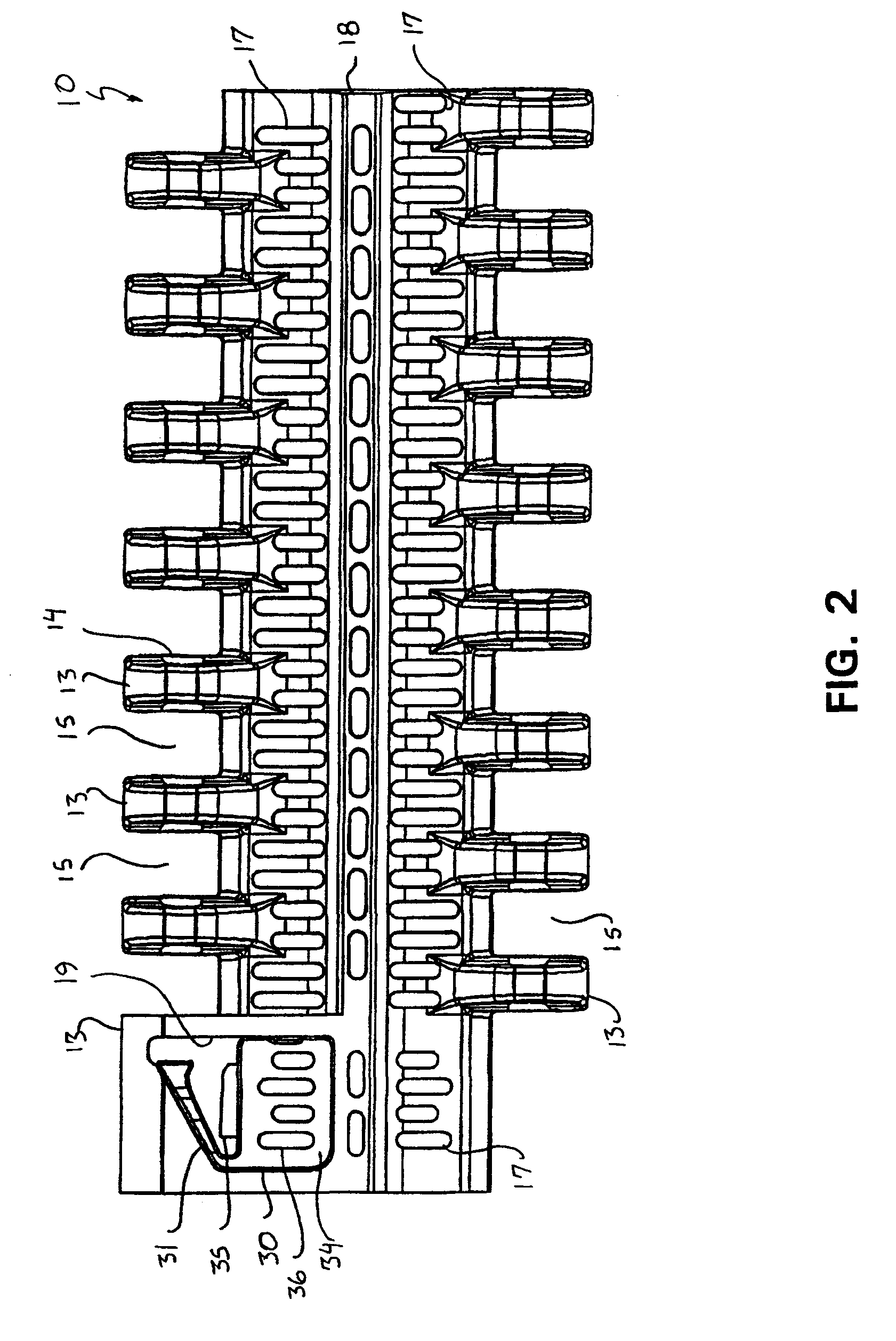
[0025]FIGS. 1 and 2 are top and bottom plan views, respectively, of an embodiment of a module 10 for a modular conveyor belt according to the present invention. As long as the module 10 has a retainer which can be flexed between a position in which it can prevent retraction of a hinge rod from the module and a position in which it permits a hinge rod to be retracted from the module, there are no particular restrictions on the shape of the module. For example, it can have the same overall shape as a wide variety of existing modules for modular conveyor belts. As such, the shape of the module 10 shown in FIGS. 1 and 2 is merely one example of many possible shapes. The illustrated module 10 has the same overall shape as that of a Series 800 Perforated Flat Top 295 module sold by Intralox, L.L.C. of Harahan, La. This module 10 has a generally rectangular outer periphery as viewed in plan and includes first and second lengthwise ends and first and second widthwise ends. In this descripti...


PUM

PropertyMeasurementUnit
Fractionaaaaaaaaaa
Fractionaaaaaaaaaa
Lengthaaaaaaaaaa

Abstract

A module for a modular conveyor belt includes a flexible retainer for retaining a hinge rod in a bore of the module. A stopper limits the bending movement of the retainer and supports the midportion of the retainer to prevent stresses generated in the retainer from exceeding its design stress.

Description

BACKGROUND OF THE INVENTION[0001]This invention relates to a module for a modular conveyor belt which has a retainer for retaining a hinge rod in the module and which enables a hinge rod to be retracted from the module without damaging the retainer.[0002]A modular conveyor belt is a conveyor belt formed from a plurality of units (referred to as modules) pivotably connected to each other end to end in series. Modular conveyor belts are popular in the product handling industry because the length of such conveyor belts can be readily adjusted by varying the number of modules making up the conveyor belts. Furthermore, a modular conveyor belt is easy to repair when worn or damaged by simply replacing any worn or damaged modules without it being necessary to replace the entire conveyor belt.[0003]The modules forming a modular conveyor belt are pivotably connected in series by elongated hinge rods which pass through aligned bores formed in the modules. Various means have been employed to p...

Claims


Application Information

Patent Timeline
IPC IPC(8): B65G17/06B23P19/00
CPCB65G17/08Y10T29/49815B65G2207/12B65G17/40
Inventor WUNSCH, PHILIP J.
Owner LAITRAM LLC
Why Eureka
Try Eureka