
Package for multiple light emitting diodes

a technology of light-emitting diodes and light-emitting diodes, which is applied in the direction of semiconductor/solid-state device details, lighting support devices, lighting and heating apparatus, etc., can solve the problems of limited brightness of existing led-based lamps, limited overall brightness of led-based lamps, and limited operation of led-based lamps

Active Publication Date: 2010-10-14
LEDENGIN
View PDF3 Cites 75 Cited by
  • Summary
  • Abstract
  • Description
  • Claims
  • Application Information

AI Technical Summary

Benefits of technology

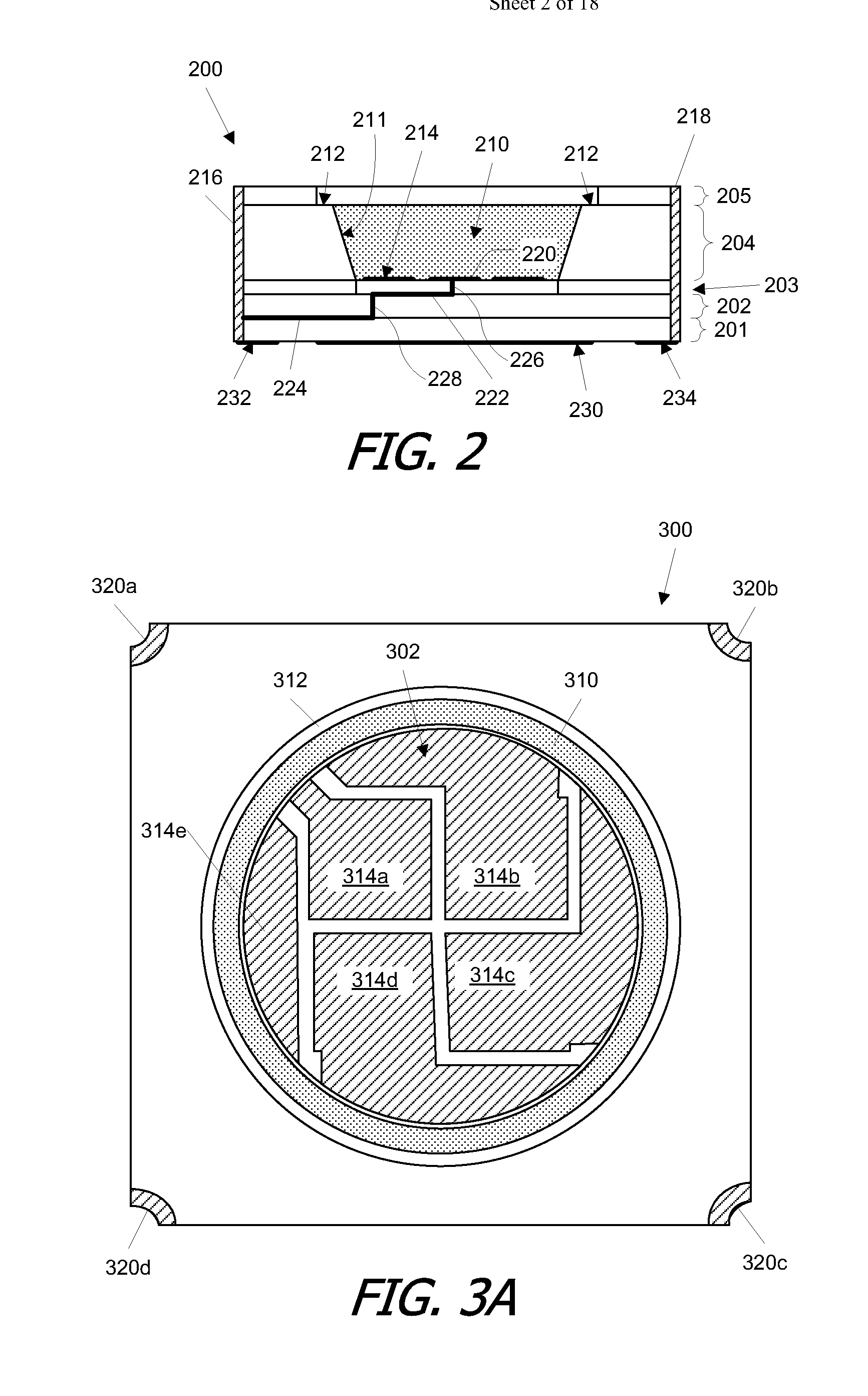
[0011]Embodiments of the present invention provide substrates and packages for LED-based light devices that can significantly improve thermal performance, allowing the LEDs to operate at higher current and therefore higher brightness. In addition, some embodiments provide improved electrical properties by providing separate electrical and thermal paths through the substrate. The separation of electrical and thermal paths further allows different operating current to be supplied to different LEDs, enhancing the ability to control the light output of the device.
[0015]Another aspect of the present invention relates to packages for use in lamps and other lighting applications. In some embodiments, a package can include a substrate (e.g., any of the embodiments described above), light devices (e.g., LEDs and / or light sensors) mounted on and electrically connected to the top-side electrical contacts, and a primary lens disposed over the light devices. A region between the light devices and the primary lens can be filled with an optically transparent medium that can provide, for example, optical index-matching and adhesive properties to hold the primary lens in position.

Problems solved by technology

Brightness of existing LED-based lamps is limited in part by problems of thermal management.
Operating LEDs produce considerable heat as well as light.
The heat must be channeled away from the LED, as overheating will damage the LED die.
Existing packages often limit the overall brightness of an LED-based lamp by limiting the amount of heat that can be dissipated.

Method used


Image

  • Package for multiple light emitting diodes
  • Package for multiple light emitting diodes
  • Package for multiple light emitting diodes

Examples


Embodiment Construction

[0025]Embodiments of the present invention provide substrates and packages for LED-based light devices that can significantly improve thermal performance, allowing the LEDs to operate at higher current and therefore higher brightness. In addition, some embodiments provide improved electrical properties by providing separate electrical and thermal paths through the substrate. The separation of electrical and thermal paths further allows different operating current to be supplied to different LEDs, enhancing the ability to control the light output of the device.

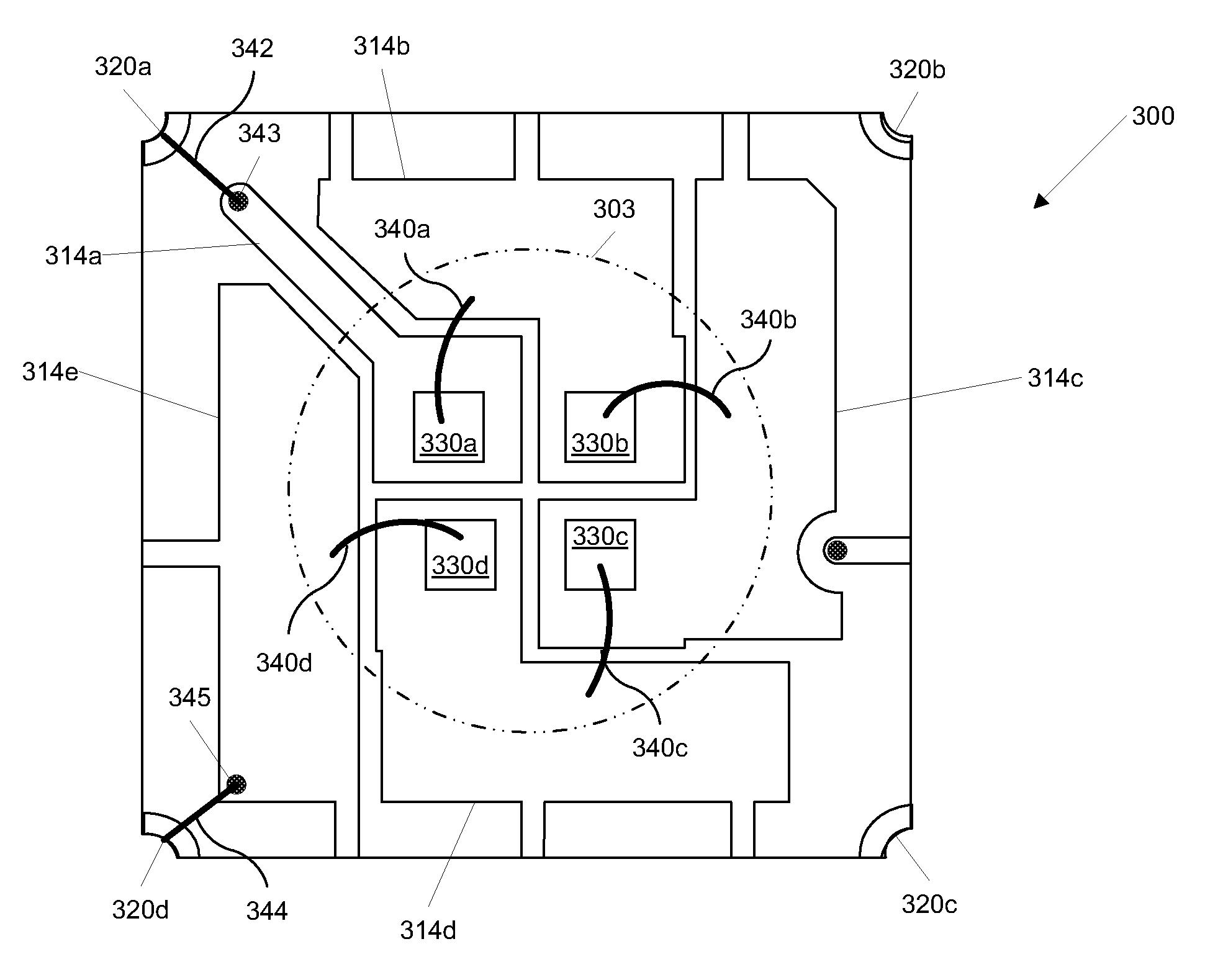
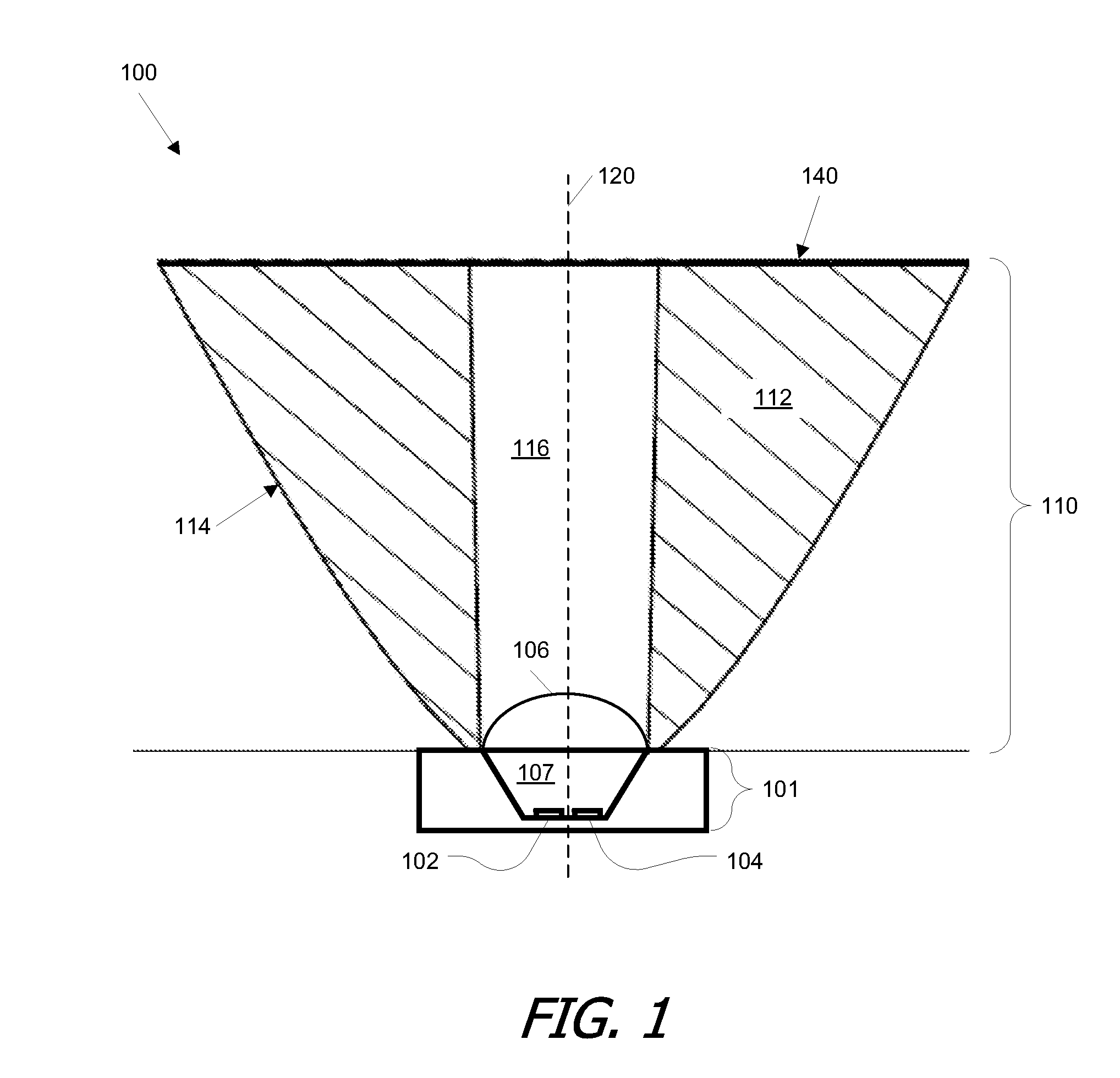
[0026]FIG. 1 is a simplified cross-sectional view of a lamp according to an embodiment of the present invention. As shown, lamp 100 includes light source substrate 101, primary lens 106, and secondary lens 110. Light source substrate 101 can include multiple LEDs, two of which, 102 and 104, are shown in FIG. 1. Any number and type of LEDs may be used. In one embodiment, each LED is a blue LED (any LED that emits light in the bl...


PUM


Abstract

Substrates and packages for LED-based light devices can significantly improve thermal performance and provide separate electrical and thermal paths through the substrate. One substrate includes multiple electrically insulating base layers. On a top one of these layers are disposed top-side electrical contacts, including light device pads to accommodate a plurality of light devices. External electrical contacts are disposed on an exterior surface of the substrate. Electrical paths connect the top-side electrical contacts to the external electrical contacts. At least portions of some of the electrical paths are disposed between the electrically insulating base layers. The electrical paths can be arranged such that different subsets of the light device pads are addressable independently of each other. A heat dissipation plate can be formed on the bottom surface of a bottom one of the base layers.

Description

CROSS-REFERENCE TO RELATED APPLICATIONS[0001]This application claims the benefit of U.S. Provisional Application No. 61 / 167,761, filed Apr. 8, 2009, entitled “Package for Multiple Light Emitting Diodes,” the disclosure of which is incorporated by reference herein in its entirety.BACKGROUND OF THE INVENTION[0002]Embodiments of the present invention relate to solid-state light devices, and more specifically to packages for solid-state light devices.[0003]A light-emitting diode (LED) is a semiconductor device that produces light when an electric current is passed therethrough. LEDs have many advantages over conventional lighting sources, including compact size, low weight, longer life time, high vibration resistance, and higher reliability. In addition to having widespread applications for electronic products as indicator lights, LEDs also have become an important alternative light source for various applications where incandescent and fluorescent lamps have traditionally dominated.[00...

Claims


Application Information

Patent Timeline
Patent Type & Authority Applications(United States)
IPC IPC(8): F21V5/00H05K1/18F21S4/00
CPCF21K9/00H05K2201/2054H01L33/62H01L33/64H01L25/0753H05K2201/10106H05K1/181H05K1/112H01L2224/48091H01L2924/19107H05K1/0271H05K1/0313H01L2924/00014H01L2924/00
Inventor YAN, XIANTAO
Owner LEDENGIN
Learn More