Fusing apparatus and image forming apparatus
- Summary
- Abstract
- Description
- Claims
- Application Information
AI Technical Summary
Benefits of technology
Problems solved by technology
Method used
Image

Examples
embodiment 1
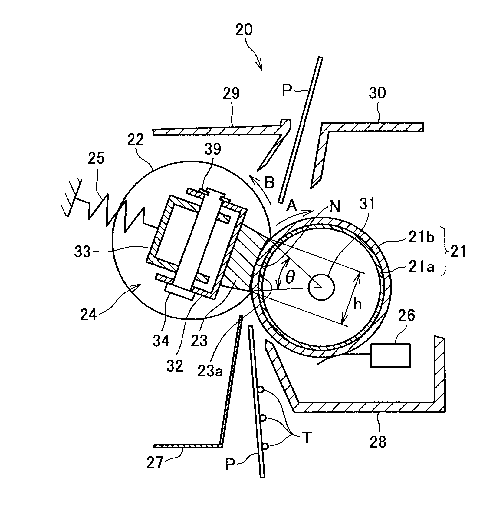
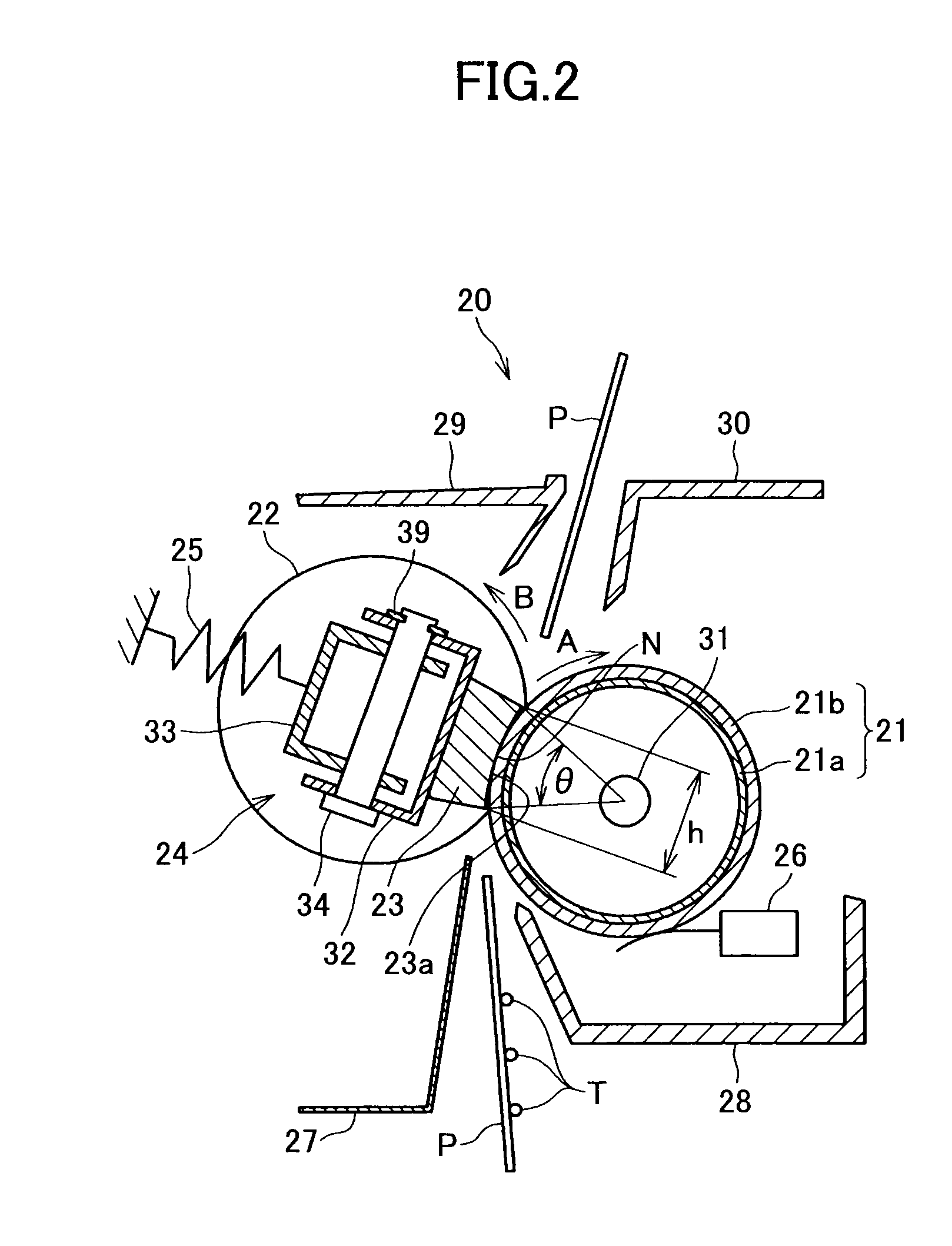
[0037]FIG. 2 is a schematic cross section of the fusing apparatus 20 according to a first embodiment of the present invention. The fusing apparatus 20 includes a fusing roller 21 in which a heater 31 is installed; an endless pressing belt 22; a pressing member 23 configured to press the pressing belt 22 onto the fusing roller 21; a support member 24 supporting the pressing member 23; a spring 25 which is a biasing unit configured to bias the support member 24; a contacting-type thermistor 26 which is a temperature detecting unit configured to detect a surface temperature of the fusing roller 21; a pair of entry guides 27 and 28; and a pair of exit guides 29 and 30.
[0038]The fusing roller 21 is a resilient roller that includes a core 21a which may be made of a steel pipe with a thickness of 0.5 mm. The core 21a is covered with a silicone rubber layer 21b having a JIS hardness of 20 degrees and a thickness of 0.8 mm. The fusing roller 21 may have an external diameter of 26.6 mm. The s...
embodiment 2
[0059]FIG. 6 illustrates a main part of the fusing apparatus according to a second embodiment of the present invention. As in the foregoing embodiment, the reference line M that passes through the intermediate positions between the top Qd of the convex surface portions D1 and the bottom Ud of the concave surface portions D2 of the pressing member 23 in the thickness direction is curved, with the central portion protruding the most.
[0060]However, the second embodiment differs from the first embodiment in that the first support member 32 is not straight but bent so that the bottom of the central portion is extended upward by a distance δ, as illustrated in FIG. 6. The thickness of the reference line M (i.e., the distance t between the reference line M and the first support member 32) may be uniform along the longitudinal direction. The amounts δp0 through δp3 of protrusion and recess of the convex surface portions D1 and the concave surface portions D2 of the pressing member 23 are se...
embodiment 3
[0061]FIG. 7 illustrates a main part of the fusing apparatus according to a third embodiment of the present invention. The third embodiment differs from the first embodiment in the supporting structure of the first support member 32 and the second support member 33. Specifically, as illustrated in FIG. 7, an arched protruding portion 40 is formed at the longitudinal central portion of the second support member 33, the protruding portion 40 extending toward the first support member 32. During assembly, the second support member 33 is placed in the first support member 32 with the protruding portion 40 facing the first support member 32. The second support member 33 may be thereafter biased toward the first support member 32 by a biasing unit (not shown), thus butting the protruding portion 40 against the longitudinal central portion of the first support member 32. As a result, the first support member 32 receives a force from the protruding portion 40 at the central portion. After as...
PUM
 Abstract
Description
Claims
Application Information
 - Generate Ideas
- Intellectual Property
- Life Sciences
- Materials
- Tech Scout
- Unparalleled Data Quality
- Higher Quality Content
- 60% Fewer Hallucinations
Browse by: Latest US Patents, China's latest patents, Technical Efficacy Thesaurus, Application Domain, Technology Topic, Popular Technical Reports.
© 2025 PatSnap. All rights reserved.Legal|Privacy policy|Modern Slavery Act Transparency Statement|Sitemap|About US| Contact US: help@patsnap.com