Linear compressor

a linear compressor and compressor technology, applied in the direction of positive displacement liquid engine, pump components, piston pump, etc., can solve the problems of weak performance of the conventional linear compressor, high manufacturing cost, complex manufacturing process, etc., to reduce the production cost of the components, simplify the installation process of the components, and high efficiency cooling force

Active Publication Date: 2010-10-14
LG ELECTRONICS INC
View PDF6 Cites 37 Cited by
  • Summary
  • Abstract
  • Description
  • Claims
  • Application Information

AI Technical Summary

Benefits of technology

The present invention provides a linear compressor that has an efficient suction muffler for stable operation at different loads. This leads to higher cooling performance. Additionally, by reducing the number of main springs used in this design, manufacturing costs are lowered and installation becomes easier.

Problems solved by technology

The technical problem addressed in this patent text relates to improving the efficiency of a linear compressor's cooling force while avoiding damage to its components caused by overload. More specifically, the issue arises because the current design uses a single suction muffler that causes fluctuations in the refrigerant mass flow, leading to unstable performance and limited effectiveness.

Method used


Image

  • Linear compressor
  • Linear compressor
  • Linear compressor

Examples


Embodiment Construction

[0034]Hereinafter, preferred embodiments of the present invention will be described in detail with reference to the accompanying drawings.

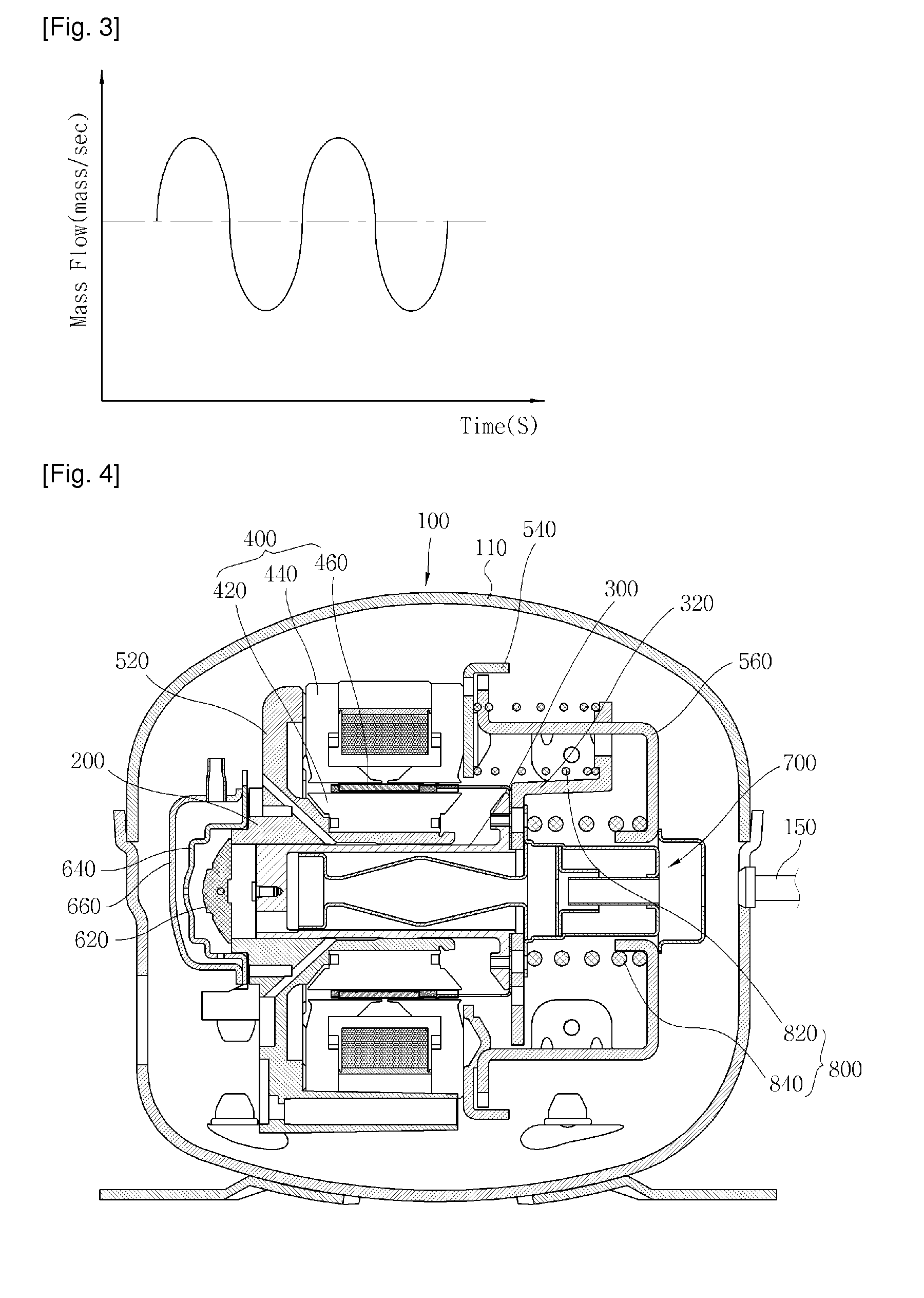
[0035]FIG. 4 is a side-sectional view illustrating a linear compressor applied with a suction muffler according to the present invention, FIG. 5 is a side-sectional view illustrating the suction muffler according to the present invention, and FIG. 6 is a graph showing a mass flow of refrigerant passing through the suction muffler according to the present invention.

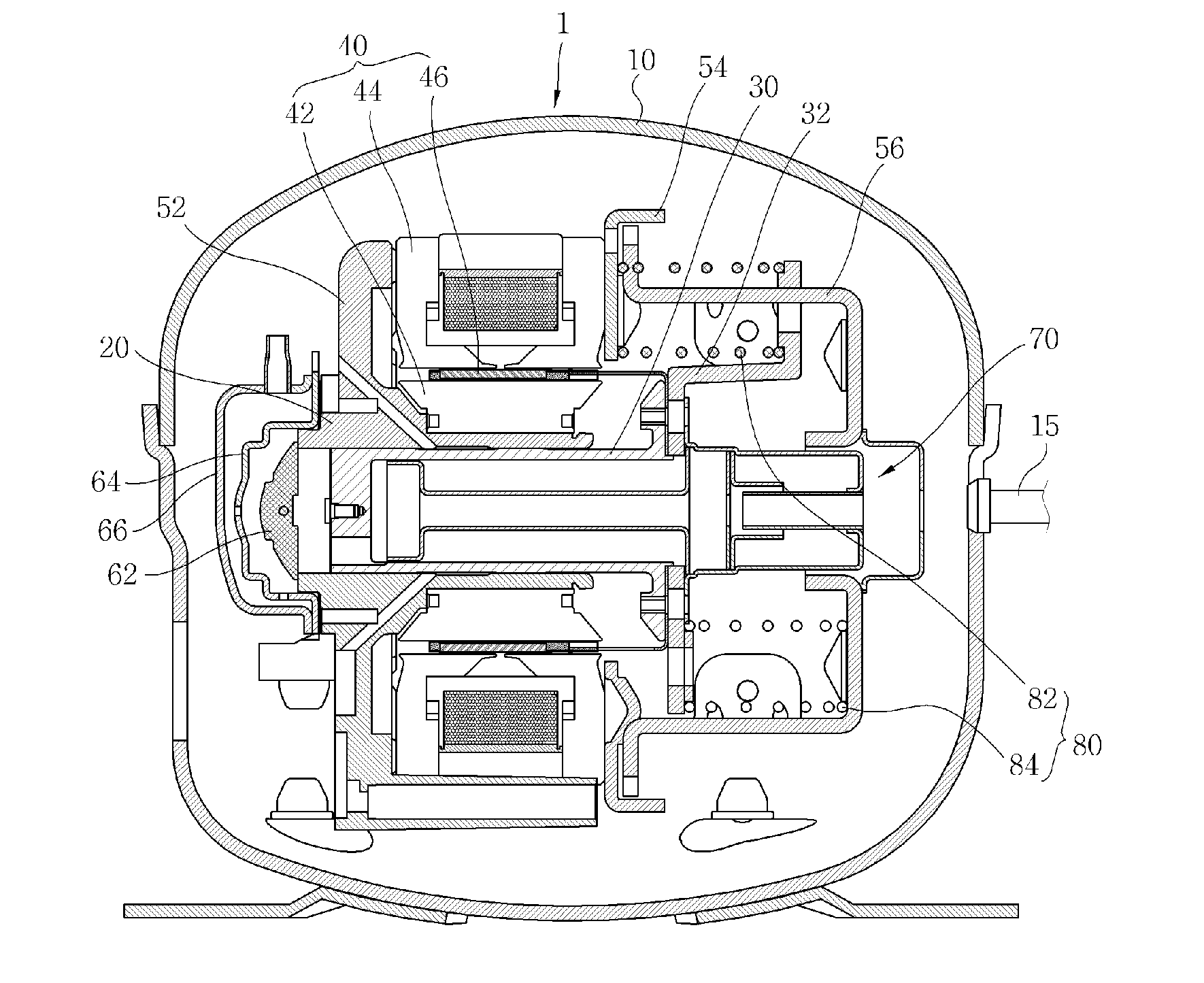
[0036]Referring to FIG. 4, in a linear compressor 100 according to the present invention, a piston 300 is linearly reciprocated inside a cylinder 200 by a linear motor 400 in a hermetic shell 110 so as to suck, compress and discharge refrigerant. The linear motor 400 includes an inner stator 420, an outer stator 440, and a permanent magnet 460 positioned between the inner stator 420 and the outer stator 440. The permanent magnet 460 is linearly reciprocated due to a mutual electromagneti...


PUM


Abstract

The present invention provides a linear compressor including: a shell (110); a fixed member installed inside the shell (110), and including a cylinder (200) for providing a compression space of refrigerant introduced into the shell (110); a moving member including a piston (300) for compressing the refrigerant sucked into the compression space inside the cylinder (200), and being linearly reciprocated with respect to the fixed member; and a suction muffler (700) positioned on a suction passage of the refrigerant inside the shell (110), a suction volume with a larger sectional area in a central portion than in both ends being defined in the suction muffler (700).

Description


Claims


Application Information

Patent Timeline
Owner LG ELECTRONICS INC
Why Eureka
Try Eureka