
Pump for dental water jet

a technology of dental water jet and pump, which is applied in the direction of dental surgery, positive displacement liquid engine, funeral device, etc., can solve the problems of noisy pump, unpleasant user experience, and inability to effectively remove food debris and bacteria

Inactive Publication Date: 2010-10-14
WATER PIK INC
View PDF109 Cites 114 Cited by
  • Summary
  • Abstract
  • Description
  • Claims
  • Application Information

AI Technical Summary

Benefits of technology

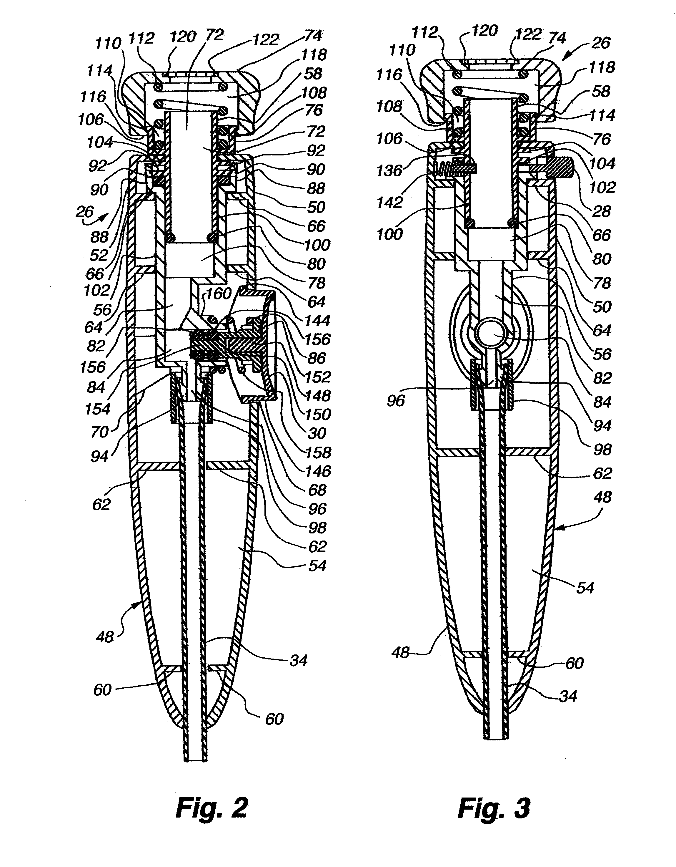
The present invention provides an apparatus for cleaning gums and teeth using a pressurized water stream. The apparatus includes a base unit with a cavity containing a pump, a flow control rotatably connected to the pump, a flow regulation conduit, a bypass valve, and a container for storing tips or other items. The apparatus can adjust the fluid pressure to the tip through the use of a reed valve. The dental water jet unit includes a housing with a cavity, a tip attachment mechanism, a visual indicator, a pause button, and a stop plunger. The invention also includes a dental water jet unit pump with an eccentric end plate and gears for selectively adjusting the fluid pressure. The dental water jet unit can be used with a reservoir and a reed valve to regulate the flow of fluid from the pump to the tip. The invention provides a convenient and effective tool for dental hygiene and cleaning.

Problems solved by technology

Traditional toothbrush and flossing often cannot reach these areas to remove the bacteria and food debris from these areas.
The pumps used in dental jet units for providing the necessary water pressures to effectively remove food debris and bacteria are often noisy.
Although the noise does not affect the dental jet's effectiveness at removing food debris and bacteria, it is often unpleasant for the user.
Further, many dental water jets may not provide any visual indication when a tip is properly seated or mated with the dental water jet (typically within a handle).
Similarly, many dental water jets may not visually indicate when the tip is properly removed.
Thus, users of such dental water jets may not fully seat the tip, leading to ineffective or weakened oral irrigation.
Additionally, the water may leak into the atmosphere between the interface of the improperly-seated tip and the handle.
Further, users of such water jets may experience difficulty fully removing the tip from the handle.
Although some dental water jets permit a user to adjust the flow of fluid from the reservoir to the tip, many do not provide fine fluid flow control.

Method used


Image

  • Pump for dental water jet
  • Pump for dental water jet
  • Pump for dental water jet

Examples


Embodiment Construction

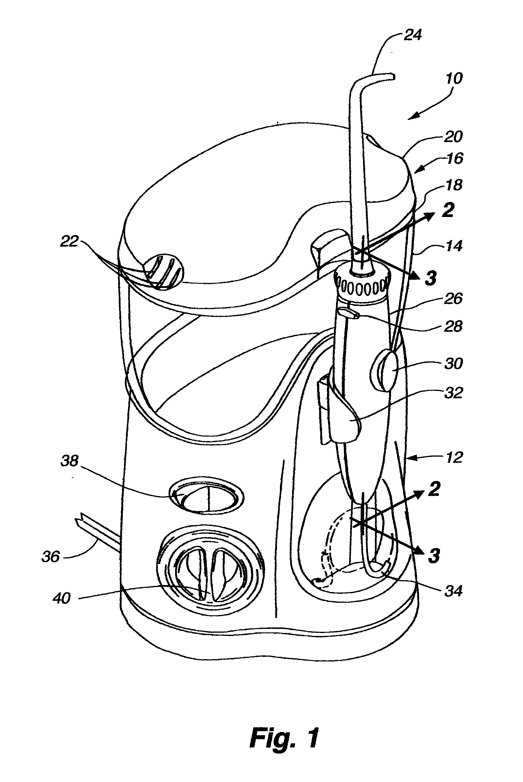
[0049]One embodiment of the present invention takes the form of an apparatus for providing a pressurized water stream for cleaning gums and teeth. The embodiment includes a base unit defining a cavity. The cavity contains a pump, which may move pressurized water from a reservoir to a tip in fluid communication with the pump. The reservoir may be supported on the base unit and in fluid communication with the pump. The pump may be connected to an electrical power source in order to power the pump. The pump may be turned on and off using a switch. A flow control knob may be turned to selectively adjust the water pressure supplied by the tip between a minimum and a maximum value. The reservoir may be removed from the base unit so that it may be filled with a fluid, such as water, from a fluid source (such as a water faucet). The reservoir may support a container for storing tips or other items.

[0050]Fluid may flow from the reservoir, through the base supporting the reservoir, along a tu...


PUM


Abstract

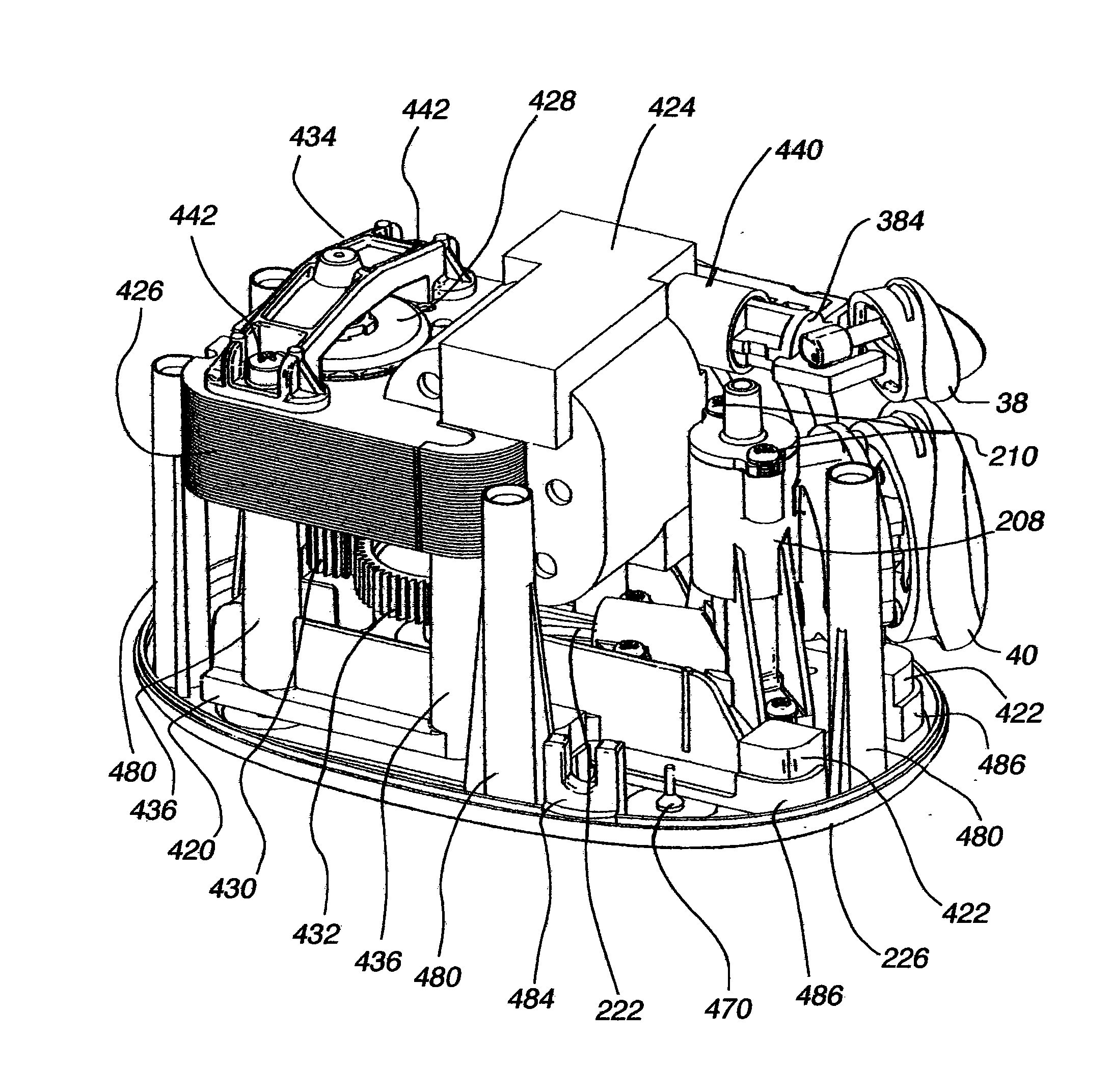
A pump for an oral irrigator includes a pump chassis, an eccentric end plate movably connected to the pump chassis, a first alignment shaft connected to the pump chassis, a second alignment shaft connected to the eccentric end plate, a first gear rotating around a longitudinal axis of the first alignment shaft, and a second gear engaging the first gear and rotating around a longitudinal axis of the second alignment shaft. By selectively moving the eccentric end plate relative to the pump chassis selectively moves the second gear relative to the first gear.

Description

CROSS-REFERENCE TO RELATED APPLICATIONS[0001]This application is a divisional of U.S. patent application Ser. No. 11 / 361,749 entitled “Water Jet Unit and Handle” filed on Feb. 24, 2006, which is hereby incorporated herein by reference in its entirety.BACKGROUND[0002]a. Field of the Invention[0003]The present invention relates generally to oral hygiene products, and more particularly to a dental water jet unit.[0004]b. Background Art[0005]Harmful bacteria often grows deep between teeth and below the gum line. Traditional toothbrush and flossing often cannot reach these areas to remove the bacteria and food debris from these areas. To overcome the limitations of toothbrushes and flossers, a dental water jet may provide a pressurized water stream to remove trapped debris and harmful bacteria from areas not easily reached by a toothbrush or flosser. Such a dental jet unit typically consists of a pump supplying pressurized water from a water reservoir to a tip. The tip has an opening tha...

Claims


Application Information

Patent Timeline
Patent Type & Authority Applications(United States)
IPC IPC(8): A61C17/02
CPCA61C1/0084A61C1/0092A61C17/02A61C17/028A61C17/0205A61C19/02F04B49/24A61C17/0202A61H13/005
Inventor BOYD, BRIANWILLIAMS, BRIAN R.TAYLOR, KURT M.
Owner WATER PIK INC
Learn More