
Medical or surgical handpiece

Active Publication Date: 2010-10-14
ARTHREX
View PDF6 Cites 13 Cited by
  • Summary
  • Abstract
  • Description
  • Claims
  • Application Information

AI Technical Summary

Benefits of technology

[0012]According to one aspect, the present medical or surgical handpiece allows a tool, in particular a drill wire, to be accommodated in the drive train of a handpiece without damaging the drill wire due to the differences in rotational speed that occur within the drive train. In addition, accommodation of a tool in a handpiece is to be made possible, in particular in its drive train independently of the handpiece and independently of the rotational speed in particular.
[0014]A drive train having a motor, preferably an electric motor with a drive shaft, is provided in the present medical or surgical handpiece. To accommodate drill wires of any length in a coupling device which is connectable or fixedly attached to the handpiece, the drive train has a through-bore passing through the handpiece. This is preferably embodied by at least one tubular shaft in the drive train and by a housing opening arranged coaxially with the drive shaft on the rear side of the handpiece. To accommodate and allow the passage of drill wires through the rotating shaft configuration without damage to the wire, the present drive train has a second shaft mounted to rotate freely relative to the first drive shaft and to rotate independently of the first drive shaft. Due to the bearing support of the second shaft by means of at least one bearing with respect to the drive train, in particular with respect to a drive shaft or a rotationally fixed component of the handpiece, the second shaft is accommodated in the drive train without being driven and is not driven by the motor and / or its gear unit and is thus able to rotate freely with respect to the drive shaft.
[0018]The present medical or surgical handpiece offers a number of substantial advantages, some of which may include the following.
[0019]Due to the bearing support of a second shaft which is mounted to rotate freely relative to a first drive shaft of a drive train, a handpiece, in particular for drill wires, is created, allowing a drill wire to be held and to be passed through the shaft configuration of the handpiece independently of the rotational speed of the drive train. The rotational speed independent passage of the handpiece ensures the coupling of a wide variety of coupling devices with different drive rotational speeds, without resulting in a difference in rotational speed between the output rotational speed of the handpiece and the drive rotational speed of a coupling device, preferably detachable.
[0020]Another advantage involves the support of the second shaft with respect to the drive shaft by means of a bearing, particularly of a roller bearing. Contact between the second shaft and the drive shaft is prevented by the bearing support within the drive shaft and / or with respect to a rotationally fixed component of the handpiece, such as that which may occur, for example, due to the insertion of the drill wire through the second shaft into the coupling device and in resetting of the handpiece in drilling the wire into the bone material and also due to the inherent imbalance of the wire in the driven state. Wear on the shaft due to possible differences in rotational speed and the resulting friction are thus prevented.

Problems solved by technology

Because of the different rotational speeds of the multiple shafts of the drive train, there has been abrasion in the past, leading to breakage of the drill wire.
One disadvantage of this design of the handpiece for driving a medical tool, in particular a surgical drill wire, has proven to be the dependence of the rotational speed acting on the wire on the shaft configuration of the drive train.
This again results in damage to the drill wire.
Another disadvantage of the embodiment known in the prior art is the lack of bearing support of the third shaft.
By inserting the drill wire through the shaft configuration, in particular through the third shaft, into the coupling device and resetting the handpiece in drilling the wire into the bone material and also because of the inherent imbalance of the wire in the driven state, contact between the first and third shafts which are arranged one inside the other and driven at two different rotational speeds is unavoidable without separate bearing of the third shaft.
This ultimately leads to increased wear on the third shaft.
Contact between the second shaft and the drive shaft is prevented by the bearing support within the drive shaft and / or with respect to a rotationally fixed component of the handpiece, such as that which may occur, for example, due to the insertion of the drill wire through the second shaft into the coupling device and in resetting of the handpiece in drilling the wire into the bone material and also due to the inherent imbalance of the wire in the driven state.

Method used


Image

  • Medical or surgical handpiece
  • Medical or surgical handpiece
  • Medical or surgical handpiece

Examples


Embodiment Construction

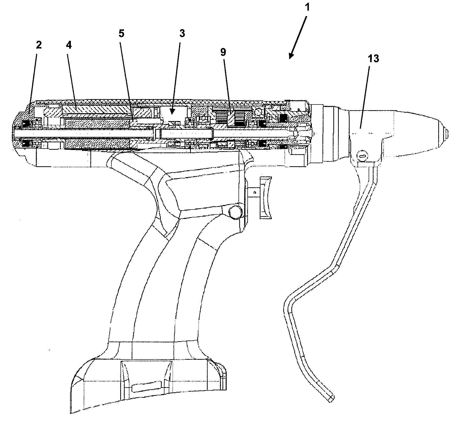
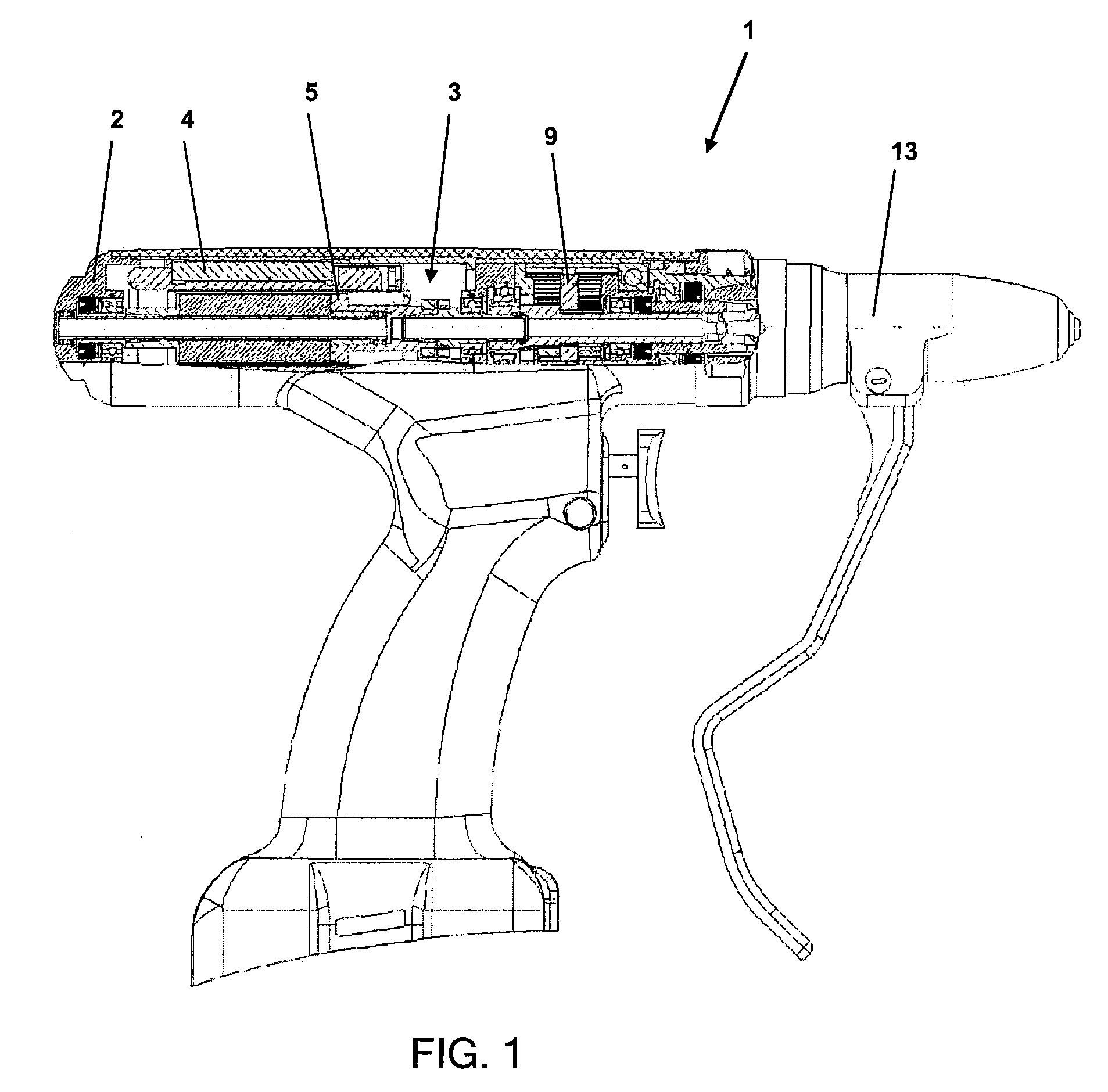
[0027]The medical or surgical handpiece 1 shown in FIG. 1 is designed as a pistol-shaped instrument having a coupling device 13, which is connectable or fixedly attached thereto. A drive train 3 for driving a tool by means of a coupling device 13 is arranged in the housing 2 of the handpiece 1. The drive train 3 comprises at least one motor 4, in particular an electric motor or an air motor, and a first drive shaft 5. In addition, the drive train 3 may have a gear 9.

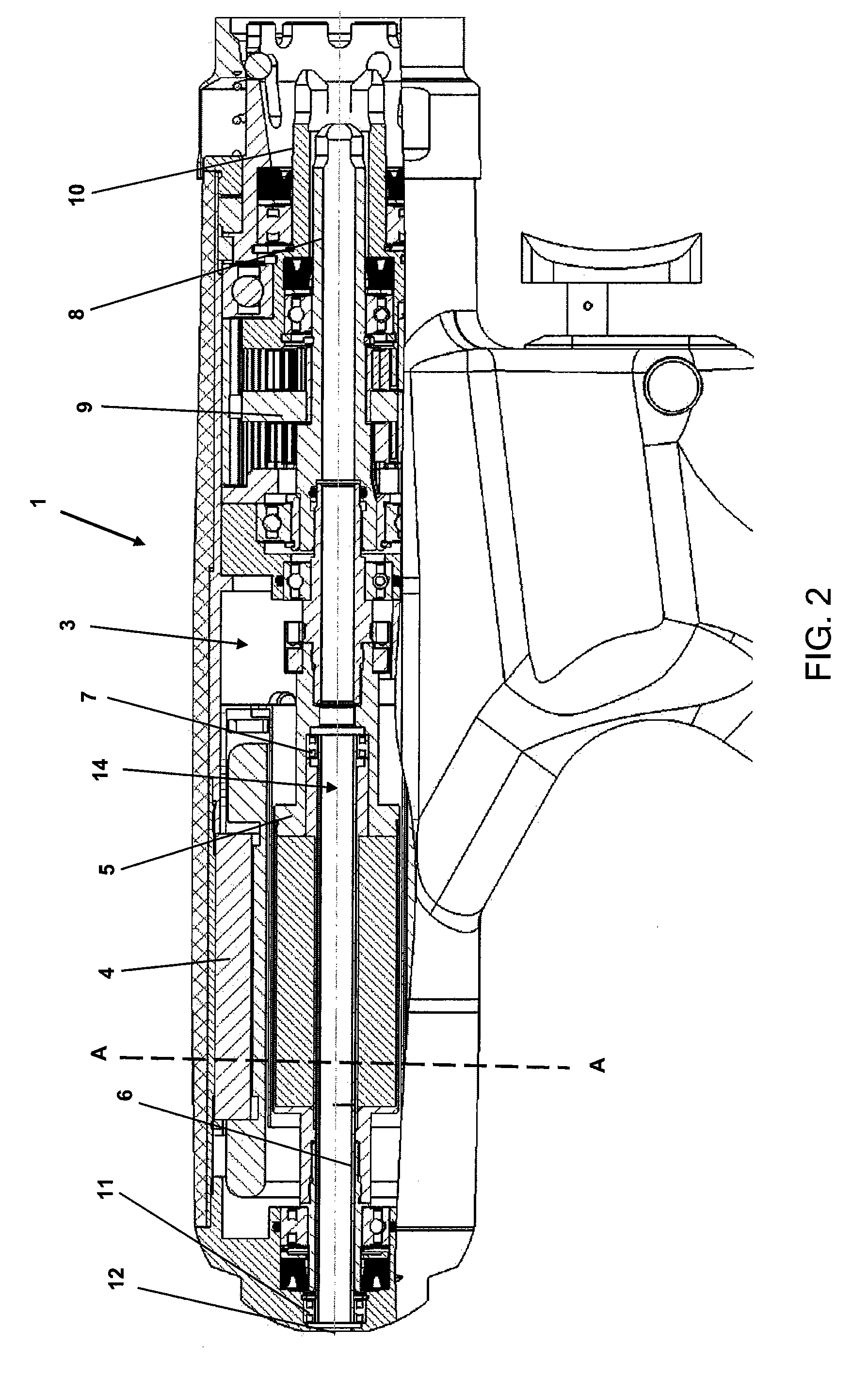
[0028]FIG. 2 shows the drive train 3 in the housing 2 of the handpiece 1. The motor 4 and its motor shaft 5 drive a first output shaft 8 and a second output shaft 10 via a gear 9. To accommodate a drill wire of any length and pass it through the drive train 3 of the handpiece 1 without damaging it due to possible differences in the rotational speeds of the multiple shafts, a second shaft 6 is mounted so it can rotate freely relative to the first drive shaft 5 by means of the bearings 7 and 11, so that the second shaft 6 ...


PUM


Abstract

A medical or surgical handpiece for driving a medical tool comprises a housing, a drive train accommodated therein and a motor. The motor includes a first drive shaft and a second shaft, the second shaft being at least partially arranged in the first drive shaft and mounted to rotate freely relative to the first drive shaft via at least one bearing, so that the second shaft is rotatable independently of the first shaft.

Description

CROSS REFERENCE TO RELATED APPLICATION[0001]The present applications claims priority from pending European Patent Application No. 09005189.7 filed Apr. 9, 2009, which is incorporated herein by reference.BACKGROUND[0002]1. Field[0003]The present invention relates to a medical handpiece, including a surgical handpiece, for driving a medical tool.[0004]2. Description of Prior Art[0005]Such medical or surgical handpieces serve to drive medical tools, e.g., saws, drills or surgical drill wires. To do so, the tools are attached to the handpiece by coupling devices. A plurality of different tools can therefore be operated by using one handpiece.[0006]Surgical drill wires are used for treating fractures in surgery. In this procedure, the drill wires are rotated, preferably by a driven handpiece, and drilled into the bone material. By repeating the sequence “drilling into the bone material, releasing the chucking device, resetting the handpiece, renewed chucking of the wire and drilling” sev...

Claims


Application Information

Patent Timeline
IPC IPC(8): A61B17/00
CPCA61B17/1624
Inventor SCHMIED, WALTERKAINHOFER, MANFRED
Owner ARTHREX
Learn More