
Method of reducing the force required to separate a solidified object from a substrate

a technology of solidified objects and force, applied in the field of system and method of manufacturing three-dimensional objects, can solve the problems of adding moving parts, introducing undesirable complexity into the system, and causing the object to deform or break

Active Publication Date: 2010-10-14
GLOBAL FILTRATION SYST
View PDF5 Cites 108 Cited by
  • Summary
  • Abstract
  • Description
  • Claims
  • Application Information

AI Technical Summary

Problems solved by technology

However, this technique requires additional moving parts and introduces undesirable complexity into the system.
However, this technique can cause the solidifiable material to solidify in contact with the reference plane, in which case the solidified material must be removed from the reference plane.
In certain cases, the separation force required to separate the solidified material from the reference plane is so great that it causes the object to deform or break.

Method used


Image

  • Method of reducing the force required to separate a solidified object from a substrate
  • Method of reducing the force required to separate a solidified object from a substrate
  • Method of reducing the force required to separate a solidified object from a substrate

Examples


Embodiment Construction

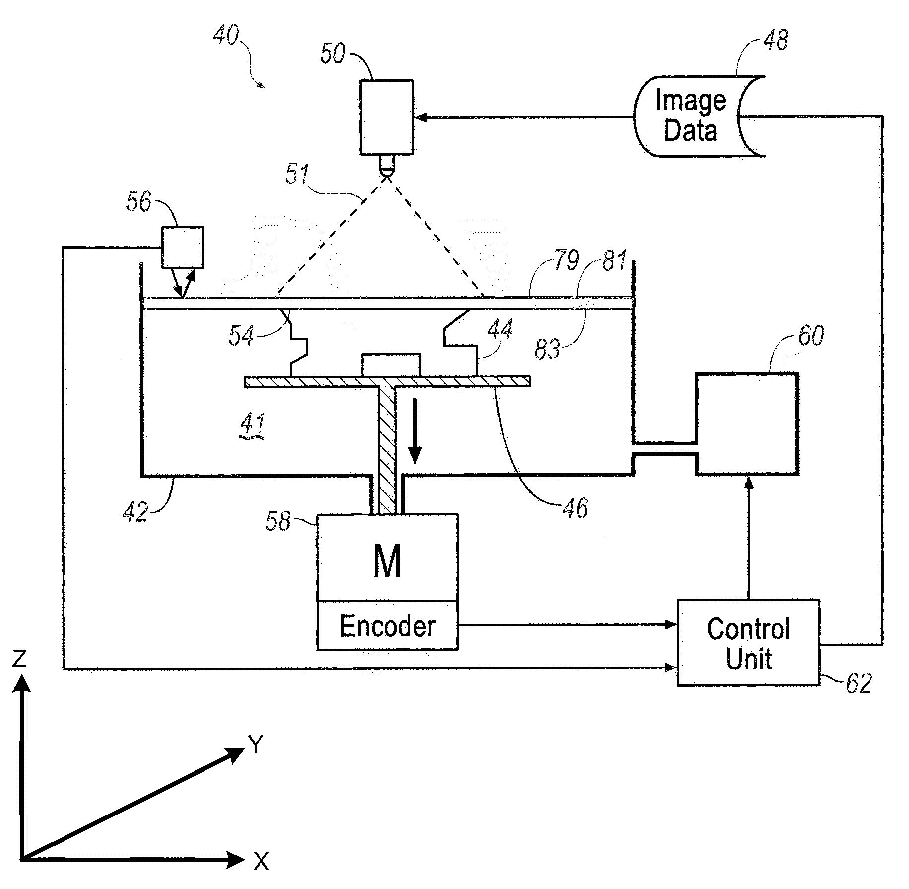
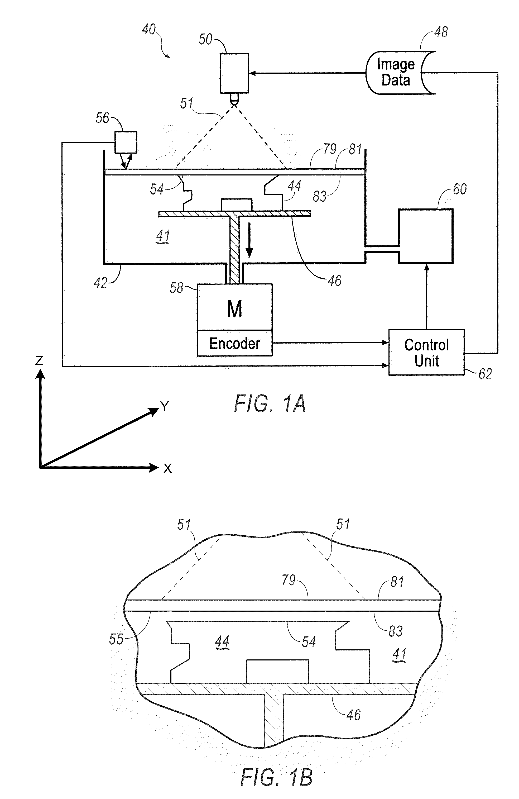
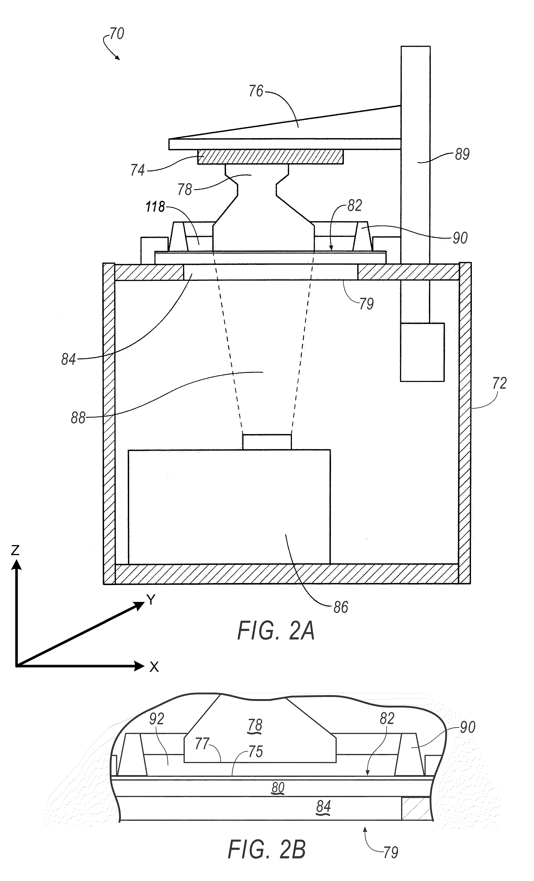
[0043]The Figures illustrate examples of a system and method for manufacturing. Based on the foregoing, it is to be generally understood that the nomenclature used herein is simply for convenience and the terms used to describe the invention should be given the broadest meaning by one of ordinary skill in the art.

[0044]The system and methods described herein are generally applicable to additive manufacturing of three-dimensional objects, such as components or parts (discussed herein generally as objects), but may be used beyond that scope for alternative applications. The system and methods generally include a pattern generator that applies energy to solidify a solidifiable material in accordance with image data that corresponds to a three-dimensional object. In accordance with the method, different positions relative to an object build axis are solidified in multiple steps, during which the build platform on which the object is built is at different positions relative to the expose...


PUM

PropertyMeasurementUnit
Thicknessaaaaaaaaaa
Volumeaaaaaaaaaa
Depthaaaaaaaaaa

Abstract

A method and apparatus for making a three-dimensional object from a solidifiable material such as a photopolymer is shown and described. In accordance with the method, positions relative to a build axis are subdivided into first and second exposure data subsets, and the first and second exposure data subsets are solidified in alternating sequences to reduce the surface area of solidified material in contact with a solidification substrate.

Description

FIELD[0001]The disclosure relates to a system and method for manufacturing three-dimensional objects, and more specifically, to a method of reducing the force required to separate a solidified object from a substrate against which the object is removably adhered.DESCRIPTION OF THE RELATED ART[0002]Three-dimensional rapid prototyping and manufacturing allows for quick and accurate production of components at high accuracy. Machining steps may be reduced or eliminated using such techniques and certain components may be functionally equivalent to their regular production counterparts depending on the materials used for production.[0003]The components produced may range in size from small to large parts. The manufacture of parts may be based on various technologies including photo-polymer hardening using light or laser curing methods. Secondary curing may take place with exposure to, for example, ultraviolet (UV) light. A process to convert a computer aided design (CAD) data to a data m...

Claims


Application Information

Patent Timeline
IPC IPC(8): G06F17/00
CPCB29C67/0088B29C33/68B33Y30/00B33Y10/00B29C64/393B33Y50/02
Inventor SHKOLNIK, ALEXANDREL-SIBLANI, ALI
Owner GLOBAL FILTRATION SYST
Learn More