[0004]One aspect of the invention is the recognition of a need for a device that creates safety around the use of pushpins, has the ability to not damage adhered articles, and is readily adaptable to be used as a pushpin or a
magnet. The systems, methods, and devices of the invention have several aspects, no single one of which is solely responsible for its desirable attributes. Without limiting the scope of the invention, certain features will now be discussed briefly. The systems, methods, and devices disclosed herein avoid the problems of past devices while adding functionality and safety.
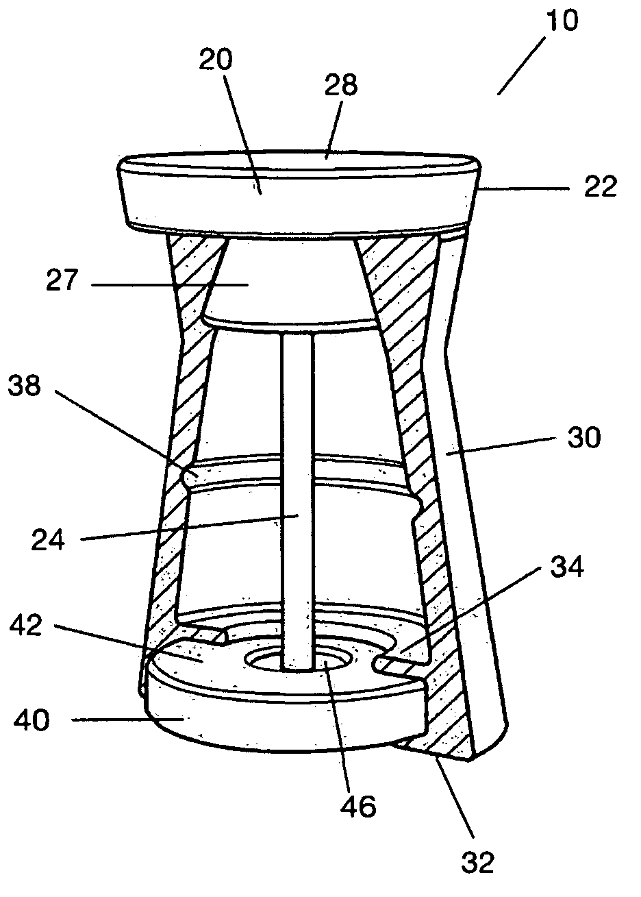
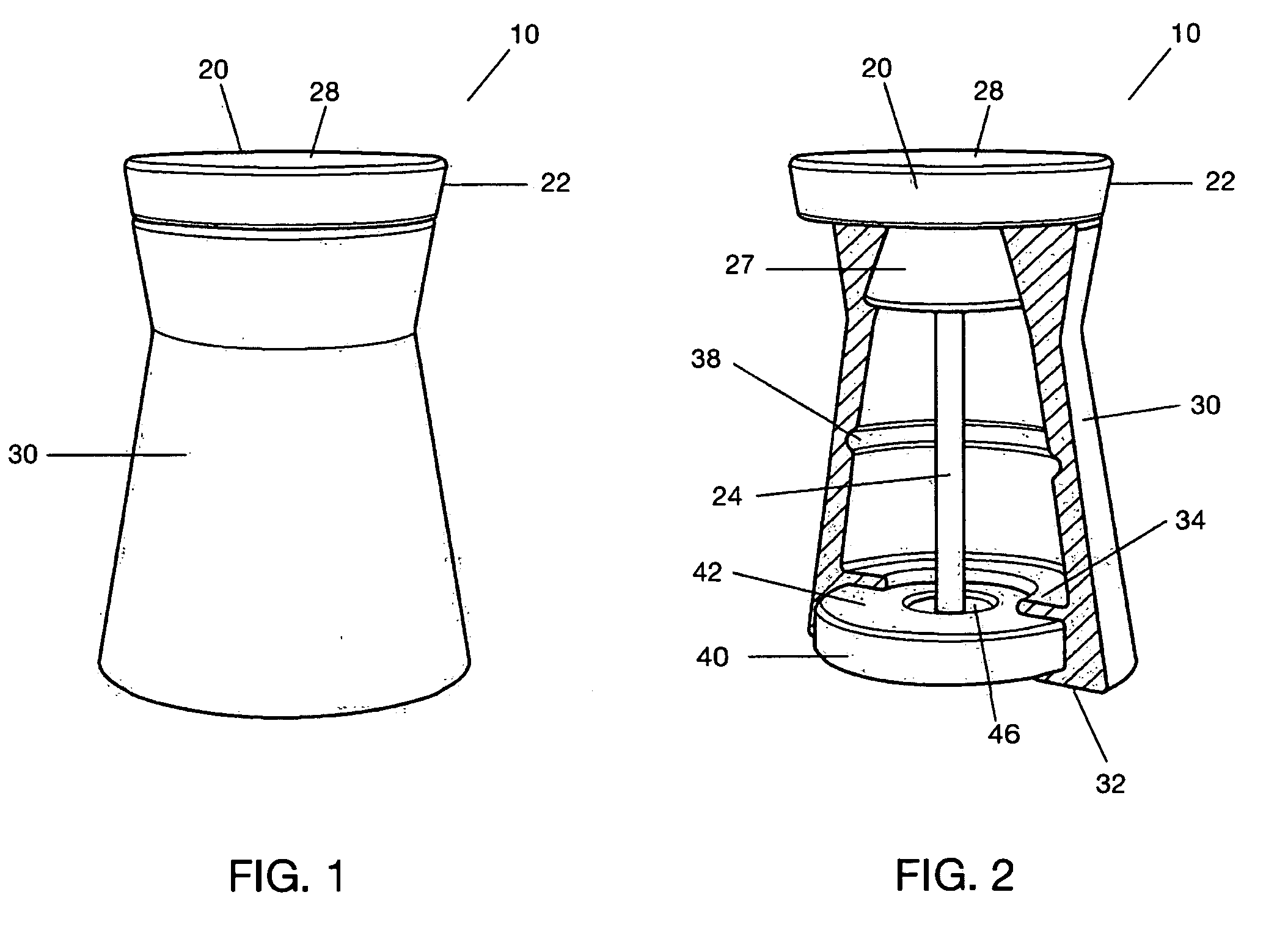
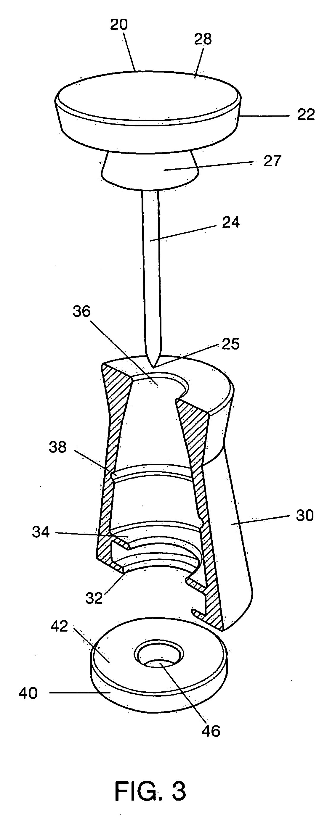
[0007]According to one embodiment, a pushpin device is adapted to
affix articles to different surfaces by piercing, by magnetic attraction, or by clamping and to enclose a pin to allow
safer handling of the device by reducing the danger of injury being inflicted by an
exposed point of the pin. The device comprises a pin head comprising magnetically susceptible material. The pin head is adapted to allow a user to apply pressure to the pin head without discomfort. A longitudinally extending pin has a proximal portion and a
distal portion. The proximal portion of the longitudinally extending pin is coupled to the pin head and the
distal portion of the longitudinally extending pin comprises a point at a distal end. The point is adapted to allow the pin to penetrate user selected articles that are to be affixed to a surface. A base comprises a magnetic material and has an aperture. The base is magnetically attracted to the pin head by a magnetic force such that when the pin head is positioned
proximate to the base the magnetic force maintains the pin head in a position proximate to the base in opposition to a countering force. The aperture is aligned with the pin and is configured to allow the pin to pass through the base as the pin head moves proximate to the base. A deformable outer member is coupled to the pin head at a first end and coupled to the base at a second end that is distal to the first end. The deformable outer member further comprises a first position wherein the pin head is spaced from the base and the deformable outer member is substantially undeformed and surrounds the entire pin along the longitudinal axis of the pin. In a second position the deformable outer member is deformed and the pin head is proximate to the base, thereby allowing the pin to extend through the aperture in the base to penetrate an article. The deformable outer member exerts the countering force on the base and the pin head.
[0008]In another embodiment, a pushpin device is adaptable to
affix articles to different surfaces and to improve user safety by reducing the danger of injury being inflicted by an
exposed point. The device comprises a head adapted to allow a user to apply pressure to the head without discomfort. A longitudinally extending fastening member comprises a point at a distal end and is coupled to the head at a proximal end. A base comprises an aperture. The aperture is configured to allow the fastening member to pass through the base as the head moves proximate to the base. An outer member is coupled to the head and the base. The outer member comprises a first position in which the head is spaced from the base and the outer member encloses a longitudinal segment of the fastening member. The outer member comprises a second position wherein the head is proximate to the base and the outer member is deformed, thereby allowing the fastening member to extend through the aperture. The outer member exerts a countering force on the base and the head. One of the head and the base comprises magnetically susceptible material and the other comprises magnetic material. A magnetic force between the head and the base maintains the outer member in the second position in opposition to the countering force.
[0009]According to another embodiment, a fastening device is preferably adapted to increase user safety and to allow articles to be affixed to various types of surfaces by piercing the article or by clamping the article. The device comprises a head comprising a first surface adapted to be safely handled by a user. A pin has a proximal portion and a
distal portion, the proximal portion of the pin is coupled to the head and the distal portion of the pin comprises a tip. A base is configured to allow at least part of the pin to extend therethrough. A flexible member has a proximal portion and a distal portion. The distal portion is coupled to the base and the proximal portion is coupled to the head. The flexible member is adapted to allow the head to be positioned proximate to the base. One of the head and the base comprises magnetic material and the other comprises magnetic material or magnetically susceptible material. The pin extends through the base when the pin head is positioned proximate to the base.
[0011]In another embodiment, a fastening device is configured to reduce the risk of injury to a user and allow a user to
affix articles to various surfaces by piercing or by friction. The fastening device comprises a head configured to allow a user to manually exert pressure on the head without discomfort. A fastening member comprises a substantially
sharp point adapted to penetrate an article. A base comprises an aperture adapted to permit the fastening member to extend therethrough. Means is provided for enclosing the fastening member in a first configuration when the fastening member is not in use to reduce the risk of user injury caused by the substantially
sharp point. Means is provided for
coupling the fastening device to a first user selected surface in the first configuration, thereby allowing the fastening device to clamp an article to be affixed to the first user selected surface. Means is provided for
coupling the fastening device to a second user selected surface in a second configuration, thereby allowing the fastening device to pierce an article to be affixed to a second user selected surface. Means is provided for holding the head proximate to the base in opposition to a resistive force that urges the base and the head apart, thereby allowing the fastening member to remain extended through the base to pierce an article to be affixed to a second user selected surface in the second configuration.

