Vehicle slide door structure

a technology for sliding doors and vehicles, applied in the direction of doors, roofs, wing accessories, etc., can solve the problems of large length of parallel links, difficult to secure a sufficient space through which a passenger can get in/out of the vehicle, etc., to reduce the overall length, and reduce the overall length

Active Publication Date: 2010-10-21
HONDA MOTOR CO LTD
View PDF32 Cites 10 Cited by
  • Summary
  • Abstract
  • Description
  • Claims
  • Application Information

AI Technical Summary

Benefits of technology

[0007]Because the link mechanism comprises the plurality of link members provided as separate components, the link members can be overlappingly collapsed as the slide door is closed, and the link members can be expanded as the slide door is opened. Thus, it is possible to reduce the overall operating range of the link members during the opening / closing operation of the slide door. Consequently, when the slide door is in the opened position, there can be secured a sufficient getting in / off opening or space, so that a passenger can get in / off the vehicle through the space in a comfortable posture.
[0008]In an embodiment, one end portion, in a slide-door opening direction, of the slide rail is curved concavely in an outward direction of the vehicle, i.e. away from the vehicle body. With the curved portion formed on the slide rail, the link mechanism can be slid smoothly on and along the slide rail during the opening / closing operation of the slide door. Thus, it is possible for the passenger or the like to smoothly perform the operation for moving the slide door outwardly of the vehicle in order to open the slide door and the operation for moving the slide door toward the interior of the vehicle in order to close the slide door. As a consequence, the opening / closing operation of the slide door can be performed smoothly.
[0009]In an embodiment, the plurality of link members comprises a vehicle-body-side link member provided on the vehicle body and a door-side link member provided on the slide door, and the vehicle-body-side link member and the door-side link member are overlappingly collapsable in response to the operation of the slide door. Because the vehicle-body-side link member and door-side link member are separate components, each of the link members can have a reduced overall length. Thus, as the slide door is closed, the link members can be overlappingly collapsed, so that the link mechanism in the collapsed position can have a reduced overall length. As a consequence, it is possible to even further reduce the overall operating range of the link members during the opening / closing operation of the slide door.
[0010]In an embodiment, the vehicle-body-side link member includes a first vehicle-body-side link and a second vehicle-body-side link that are disposed in parallel to each other, and the door-side link member includes a first door-side link and a second door-side link that are disposed in parallel to each other. Thus, the slide door can be securely supported by the link mechanism during the opening / closing operation of the slide door, so that it is possible to avoid unwanted rattling movement of the slide door during the opening / closing operation.
[0011]In an embodiment, when the slide door is in the opened position with the link mechanism placed in the expanded position, the door-side link member extends in an opening / closing direction of the slide door while the vehicle-body-side link member extends in an inward-outward (or width) direction of the vehicle. In this way, it is possible to prevent unwanted rattling movement of the slide door during the opening operation of the slide door.

Problems solved by technology

However, to open the slide door, there is a need to move the slide door a predetermined distance away from the vehicle body, and the two parallel links have to have great lengths.
Therefore, an operating range of the two parallel links necessary for opening the slide door would become considerably great, which undesirably makes it difficult to secure a sufficient space through which a passenger can get in / off the vehicle (such a space will hereinafter be referred to as “getting in / off opening” or “getting in / off space”).

Method used


Image

  • Vehicle slide door structure
  • Vehicle slide door structure
  • Vehicle slide door structure

Examples


Embodiment Construction

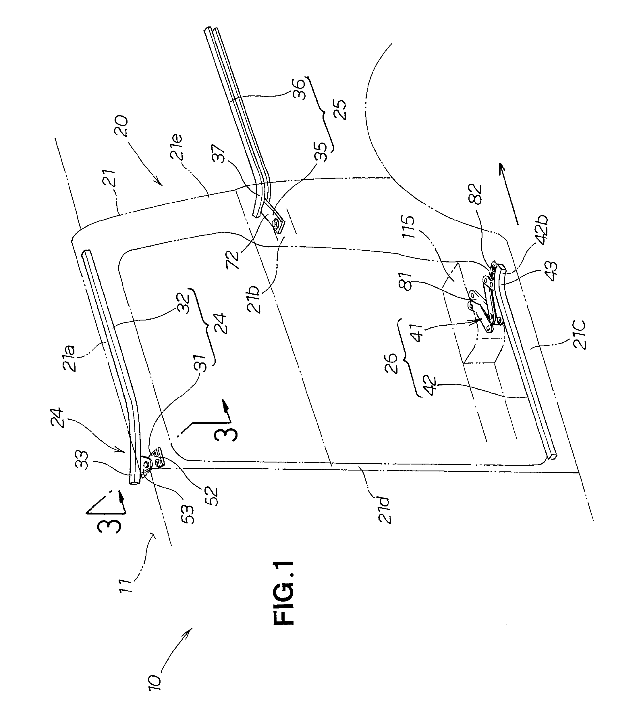
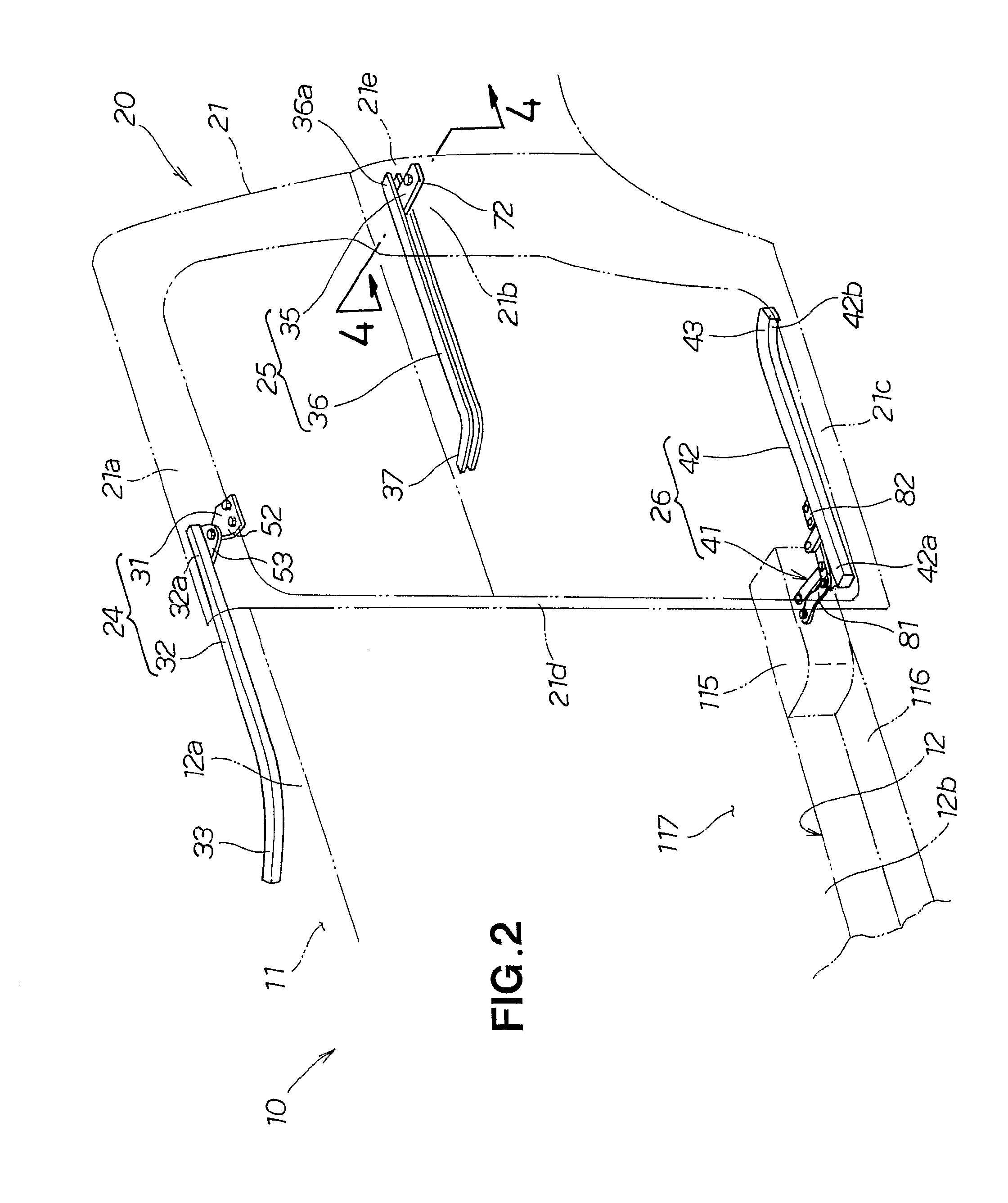
[0024]Reference is now made to FIG. 1 showing in perspective an embodiment of a vehicle slide door structure of the present invention in a closed position, and to FIG. 2 showing in perspective the vehicle slide door structure in an opened position.

[0025]The vehicle 10 has a slide door opening section 12 formed in the left side of a vehicle body 11, and it includes the vehicle slide door structure 21 provided on the left side of the vehicle body 11 for opening and closing the slide door opening section 12. The slide door opening section 12 provides a getting in / off space or opening through which a passenger gets in and off the vehicle, and it is formed in a substantially rectangular shape with upper end lower edge regions 12a and 12b and front and rear edge regions.

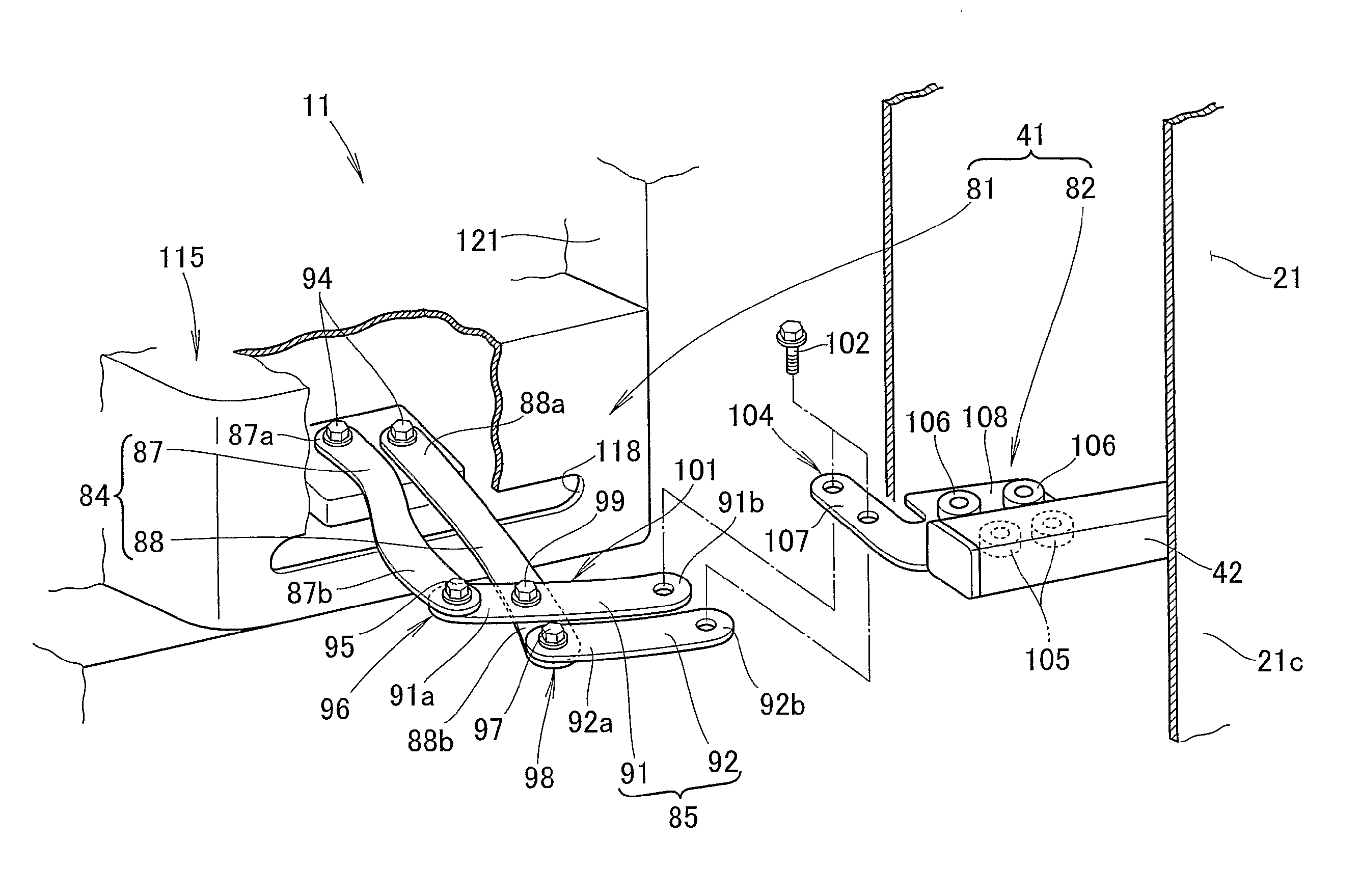
[0026]The vehicle slide door structure 20 includes a slide door 21 for opening and closing the slide door opening 12, an upper support unit 24 for supporting an upper portion 21a of the slide door 21, an intermediate (i.e....


PUM


Abstract

Vehicle slide door structure includes a lower slide rail (42) provided on a slide door (21), and a link mechanism (81) provided between a vehicle body (11) and the slide rail (42). The link mechanism (81) is pivotably connected at one end portion to the vehicle body (11) and pivotably and slidably connected at the other end portion to the slide rail (42). The link mechanism (81) includes a plurality of link members (84, 85) and connection sections (96, 98, 101) where the link members are pivotably connected with each other between the one end portion and the other end portion.

Description

TECHNICAL FIELD[0001]The present invention relates to vehicle slide door structures for openably / closably supporting a slide door on a vehicle body.BACKGROUND ART[0002]Among the conventionally-known vehicle slide door structures are ones where a guide rail extending in a front-rear direction of the vehicle is provided on a slide door and connected to the vehicle body via a parallel link mechanism. As disclosed, for example, JP 09-277833 A, the parallel link mechanism includes two parallel links that are pivotably connected at their respective proximal end portions to the vehicle body and pivotably and slidably connected at their distal end portions to the guide rail.[0003]With the slide door structure disclosed in JP 09-277833 A, a slide door opening section can be opened by the two parallel links being pivoted about the proximal end portions to move the slide door away from the vehicle body and then the slide door being slid toward the rear of the vehicle along the distal end porti...

Claims


Application Information

Patent Timeline
Patent Type & Authority Applications(United States)
IPC IPC(8): B60J5/06E05F11/54
CPCB60J5/06E05D3/16E05Y2900/531E05D2003/166E05D2015/1092E05D15/1081
Inventor YOSHIOKA, JUNICHI
Owner HONDA MOTOR CO LTD
Why Eureka
Try Eureka