MEMS inertial sensor with frequency control and method

a technology of inertial sensor and frequency control, applied in the field of microelectromechanical system (mems) devices, can solve the problems of inability to control the frequency, power, frequency and amplitude stability of an asic based oscillator operating at several hundred hz, and the prohibitively expensive inclusion of low frequency filters

Inactive Publication Date: 2010-10-21
NORTH STAR INNOVATIONS
View PDF4 Cites 77 Cited by
  • Summary
  • Abstract
  • Description
  • Claims
  • Application Information

AI Technical Summary

Problems solved by technology

In addition, the silicon die area, power, frequency and amplitude stability of an ASIC based oscillator operating at several hundred Hz is prohibitive

Method used


Image

  • MEMS inertial sensor with frequency control and method
  • MEMS inertial sensor with frequency control and method
  • MEMS inertial sensor with frequency control and method

Examples


Embodiment Construction

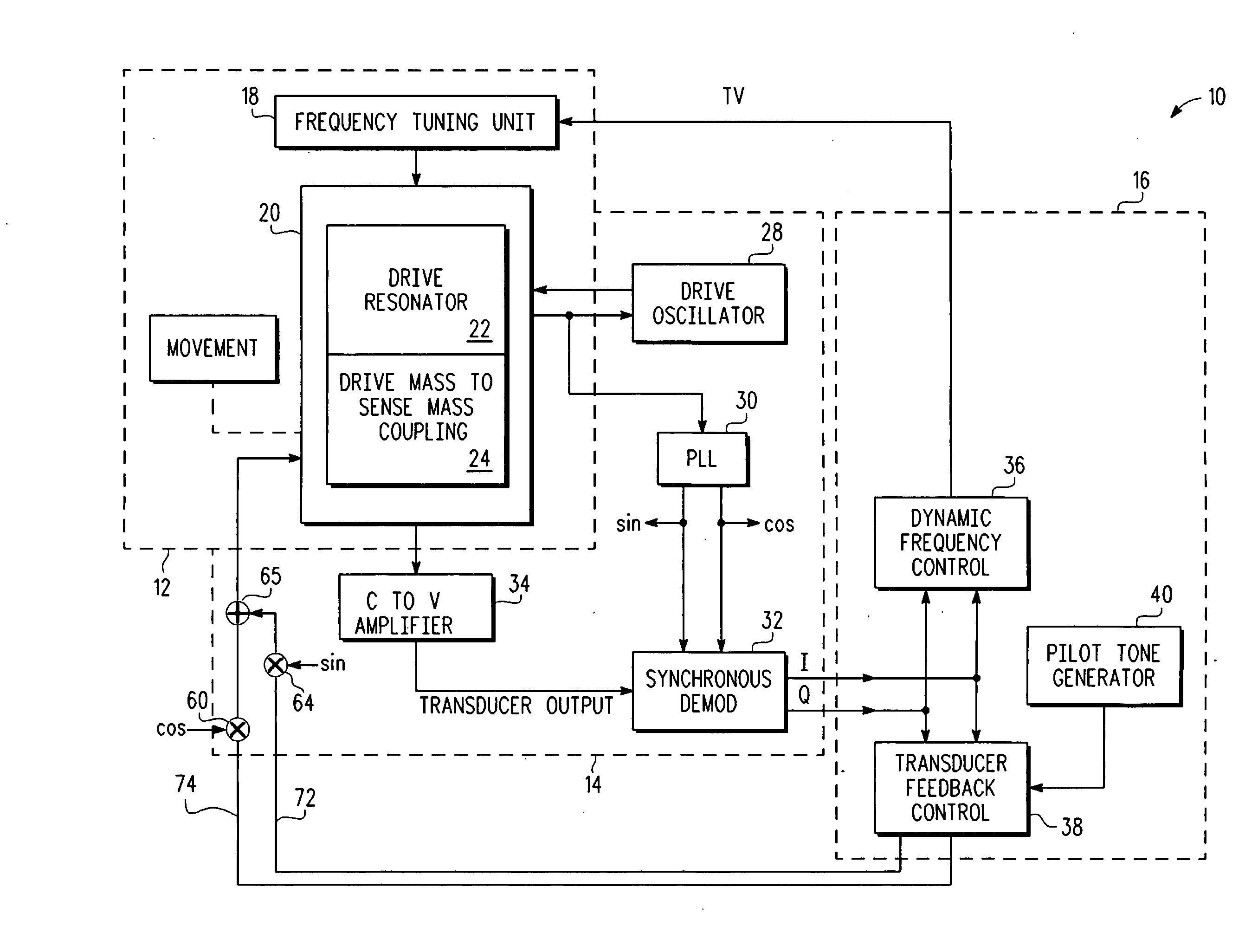
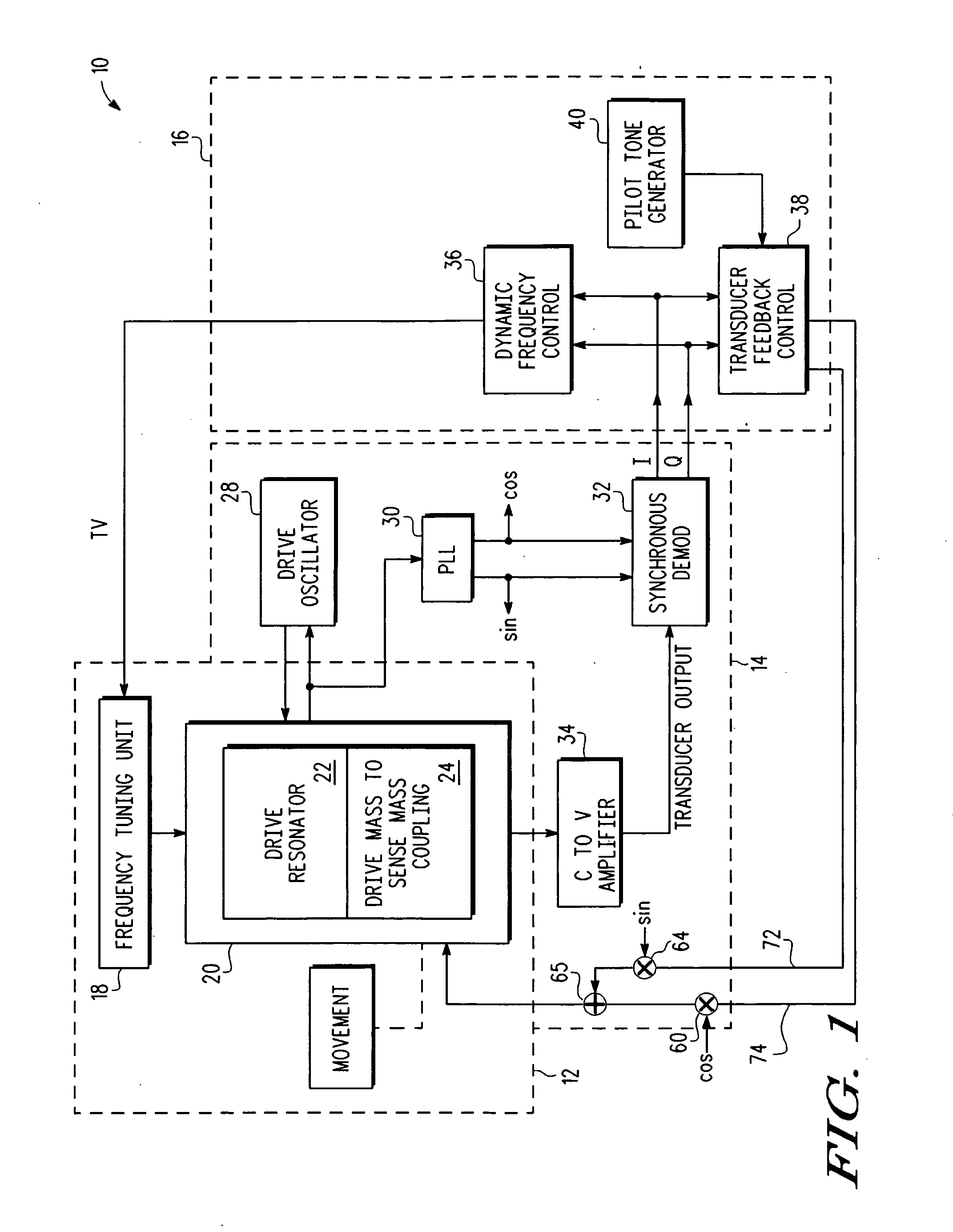
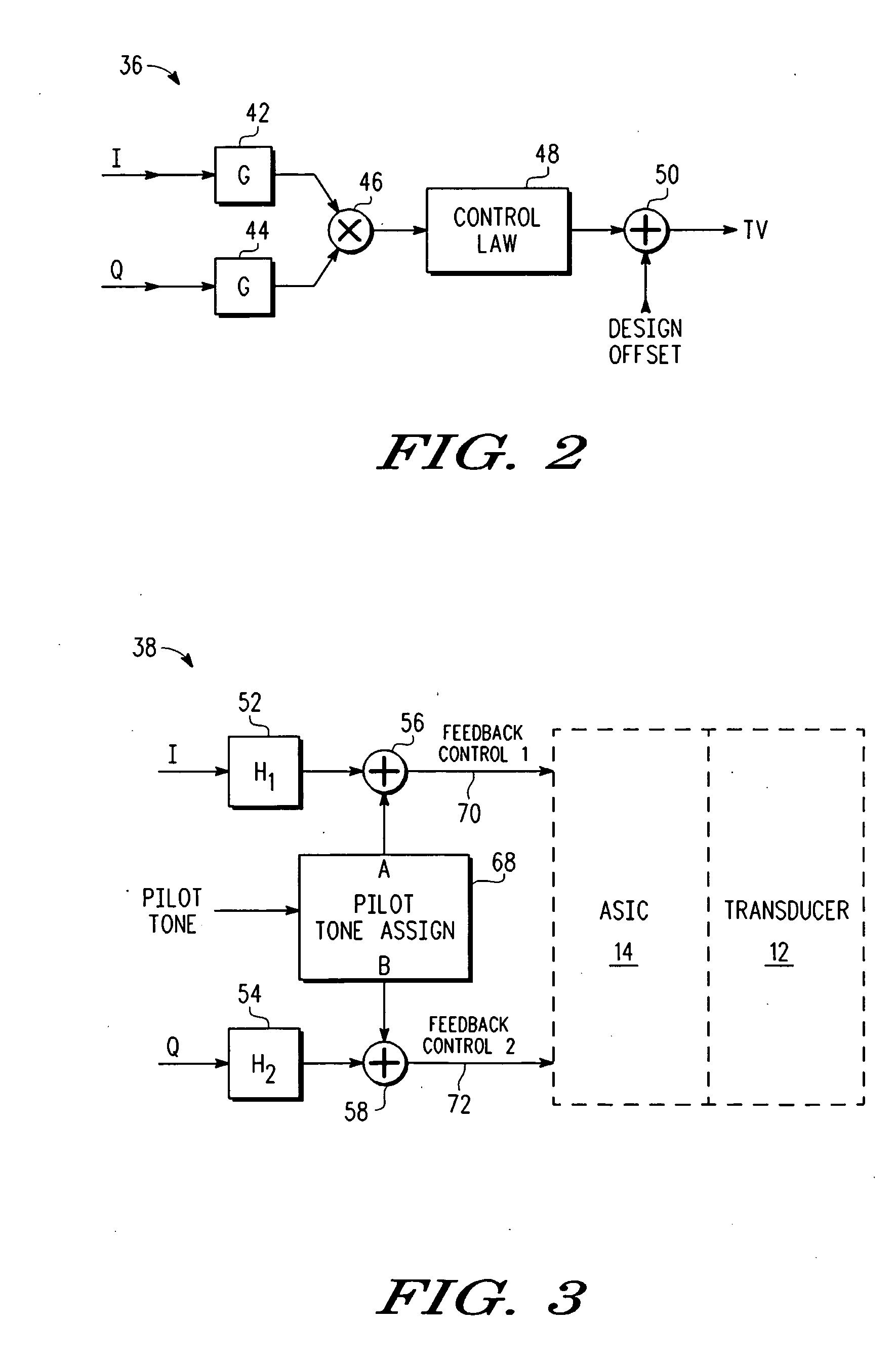
[0013]In one aspect, an inertial sensor uses feedback to establish a predetermined differential between a sense resonant frequency, which is the frequency of highest gain, and a drive frequency. A pilot tone is input to a sense resonator which generates a testing signal which is then sensed on an output of the sense resonator. The testing signal is processed to provide a frequency measurement signal that is a measure of a difference between the drive frequency and the sense resonant frequency. This frequency measurement signal is demodulated by the drive frequency to generate a frequency offset signal that is used in a control law to generate a frequency adjust signal. The frequency adjust signal is used as feedback to control the sense resonant frequency. This feedback process is continuous so that as ambient conditions change, such as a temperature change, the difference between the sense resonant frequency and the drive frequency can be maintained at the desired amount. At power ...


PUM


Abstract

An inertial sensor has a transducer with a sense resonator. The sense resonator is oscillated. A signal responsive to the oscillation is provided. A first baseband signal and a second baseband signal are provided responsive to the signal responsive to the oscillation of the sense resonator. A signal for controlling a resonance frequency of the sense resonator is provided responsive to performing a Goertzel algorithm on the first baseband signal and the second baseband signal. One use of controlling the resonance frequency is to control an offset between the resonance frequency of the sense resonator and the frequency of the oscillation of drive masses in the sense resonator. Using the Goertzel algorithm is particularly efficient in controlling the resonance frequency.

Description

BACKGROUND[0001]1. Field[0002]This disclosure relates generally to micro-electro-mechanical systems (MEMS) devices, and more specifically, to a MEMS inertial sensor with frequency control and method.[0003]2. Related Art[0004]In the development of MEMS inertial sensors, a need has arisen to dynamically measure the frequency offset between the drive and sense resonators in a MEMS gyroscope. It would be desirable to provide such dynamic measurement that is characterized by one or more of the following: 1) does not interfere with normal MEMS gyro operations; 2) does not corrupt the MEMS gyro data; 3) tunable and adaptable without hardware design modifications; 4) useful for manufacturing calibration; 5) can be calibrated to absolute frequency offsets; and 6) can recover the injected frequency, reject data and spurious signals, and achieve the same at very low cost.[0005]Further in connection with MEMS gyroscopes, it would be desirable to provide a tunable, low frequency oscillator to al...

Claims


Application Information

Patent Timeline
IPC IPC(8): G01C19/56
CPCG01C19/56G01C19/5776
Inventor HAYNER, DAVID A.KRAVER, KEITH L.MIJUSKOVIC, DEJAN
Owner NORTH STAR INNOVATIONS
Why Eureka
Try Eureka