
Vehicle child seat

a child seat and seat technology, applied in the field of vehicle child seats, can solve the problems of inoperable belt tensioning arrangement and restricted use of child seats, and achieve the effect of avoiding mounting errors

Inactive Publication Date: 2010-10-21
RECARO CHILD SAFETY
View PDF5 Cites 31 Cited by
  • Summary
  • Abstract
  • Description
  • Claims
  • Application Information

AI Technical Summary

Benefits of technology

[0010]The object of the invention is to improve a vehicle child seat with a belt tensioning function, in particular with regard to its universal use and the avoidance of mounting errors.
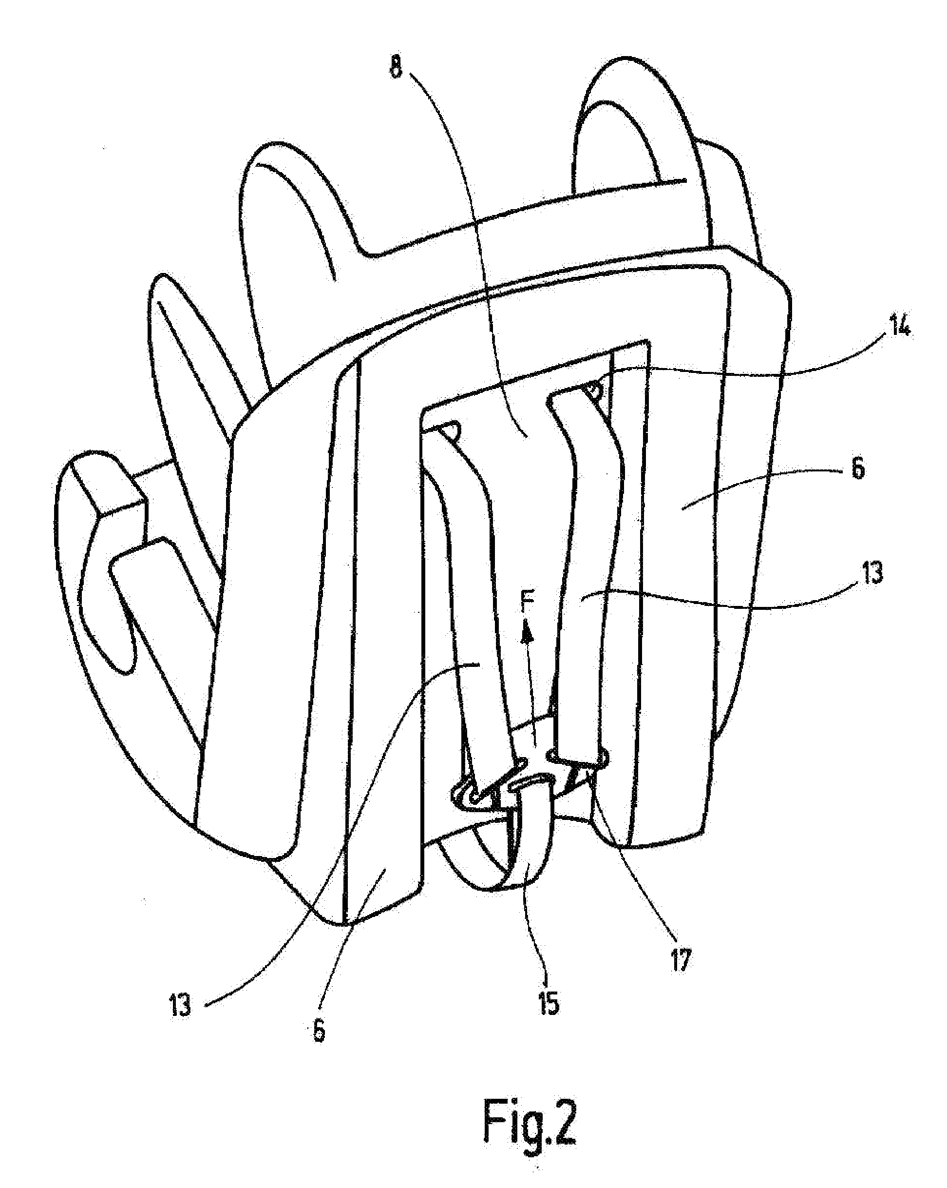
[0012]As all components of the belt tensioning device required for the belt tensioning function are fastened to or in the child seat and may be removed therewith from the vehicle, the child seat is able to be used universally in all vehicle models and on all seats. The attachment of the child seat to belt tensioners, sensor devices or control units integrated in the vehicle is dispensed with, whereby errors when mounting the child seat in the vehicle are avoided. The monitoring of the operating capability of the belt tensioning device may take place outside the vehicle, as the child seat represents a self-contained system. An additional belt force limiter integrated in the belt tensioning device effectively limits the belt forces acting on a child strapped into the child seat. During or immediately after the belt tensioning, individual belt portions of the belt system yield again when a limit force is exceeded, so that injuries of the child due to high belt forces are avoided.

Problems solved by technology

If this inadvertently does not take place, the belt tensioning arrangement is inoperational.
This is frequently not the case, however, in particular with rear seats of passenger motor vehicles, so that the use of the child seat remains restricted to specific vehicle models and / or to the front seats.

Method used


Image

  • Vehicle child seat
  • Vehicle child seat
  • Vehicle child seat

Examples


Embodiment Construction

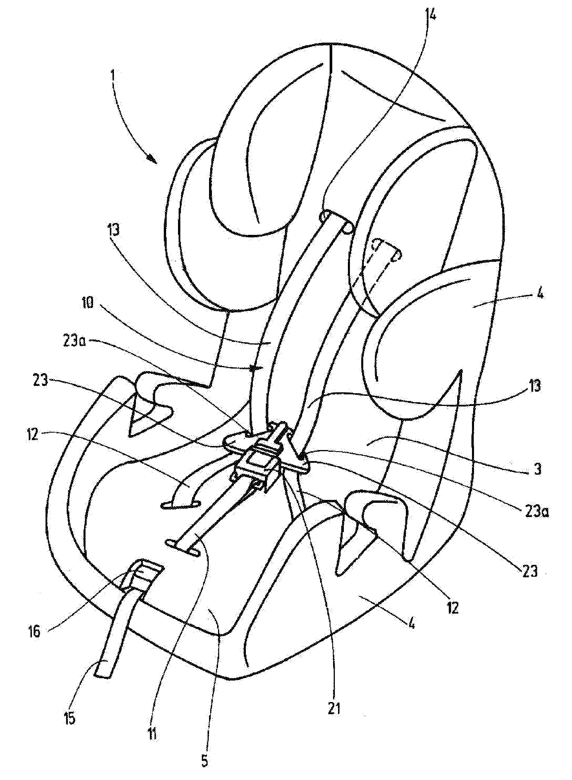
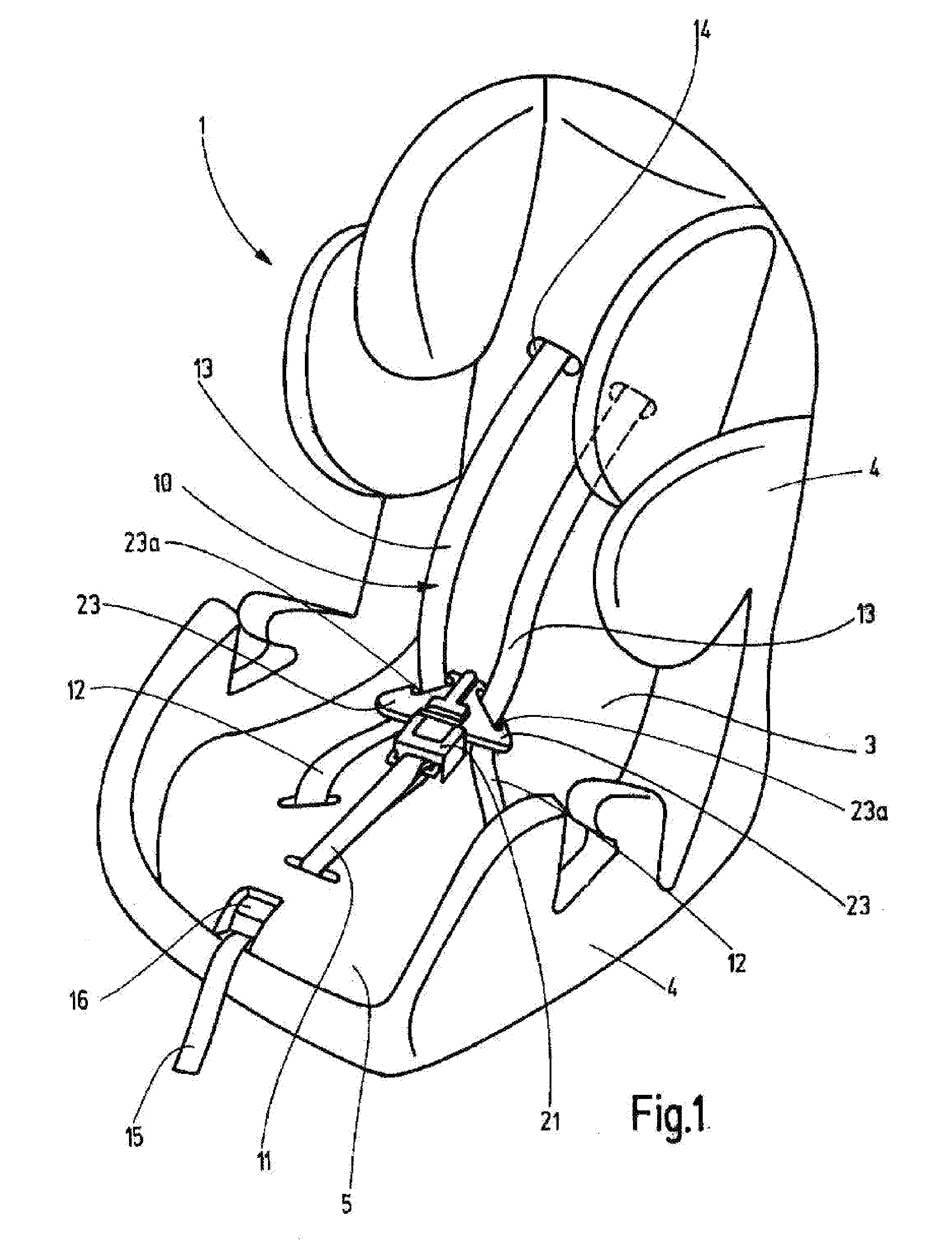
[0031]Referring to the drawings in particular, a vehicle child seat 1 shown in FIG. 1 for the transport of toddlers or children is positioned during mounting in the vehicle in the direction of travel, directly on the vehicle seat and fixed via the vehicle belt system which is present, in particular a 3-point belt. Alternatively, the child seat may be fastened indirectly onto the vehicle seat by means of a child seat base fastened to the vehicle seat or to the vehicle structure. In a modification of the exemplary embodiments described below, the vehicle child seat may also be fastened by means of a mechanical rapid fastening system, as is known for example by the term ISOFIX, to the vehicle seat or the child seat base. ISOFIX is standardized in the ISO standard 13216.

[0032]The directional information used below relates to the mounting of the vehicle child seat on the vehicle seat in the conventional direction of travel of the vehicle.

[0033]The structure of the child seat 1 consists o...


PUM


Abstract

A vehicle child seat is provided for directly or indirectly fastening to a vehicle seat and / or a vehicle structure. The vehicle child seat includes a backrest, a seat surface, an integrated belt system for fastening a child in the vehicle child seat and a belt tensioning device (31). The belt tensioning device (31) includes a trigger sensor, an energy storage device and a tensioning mechanism which, when exceeding a defined force acting on the vehicle child seat, in particular a crash force, abruptly tensions the belt system. All components of the belt tensioning device (31) required for the belt tensioning function being fastened to or in the vehicle child seat and being able to be removed therewith from the vehicle. A belt force limiting function is incorporated in the belt tensioning device (31). After triggering the belt tensioning device (31) when exceeding a limit force Fgrenz on the belt portion (11, 12, 13, 15) at least one belt deflector (137, 171) is displaced sufficiently far in the direction of a normal position, until the limit force Fgrenz has fallen below or the belt deflector (137, 171) has completely reached its normal position.

Description

CROSS REFERENCE TO RELATED APPLICATIONS[0001]This application claims the benefit of priority under 35 U.S.C. §119 of German Patent Application DE 10 2009 017 601.2 filed Apr. 16, 2009, the entire contents of which are incorporated herein by reference.FIELD OF THE INVENTION[0002]The invention relates to a vehicle child seat for directly or indirectly fastening to a vehicle seat and / or a vehicle structure.BACKGROUND OF THE INVENTION[0003]Vehicle child seats, as are used for securing children in passenger vehicles, for example, are generally known. For securing the child in the child seat, either the belt system of the vehicle itself or an integrated child seat belt system is used. The child seat is positioned in the vehicle either directly onto the vehicle seat or indirectly onto a child seat base fastened in the vehicle, as is disclosed for example in DE 10 2006 011 520 A1. The fastening of the child seat and optionally of the child seat base in the vehicle takes place by means of th...

Claims


Application Information

Patent Timeline
Patent Type & Authority Applications(United States)
IPC IPC(8): B60N2/28B60R22/46
CPCB60N2/2812B60N2/2851B60R22/105B60N2/2884B60N2/273
Inventor VOGT, THOMASGEBHARDT, STEFANPOHNER, JENS
Owner RECARO CHILD SAFETY
Learn More