Photoelectric measuring machine for precision transmission chain

A photoelectric measurement and precision transmission technology, applied in the direction of machine gear/transmission mechanism testing, etc., can solve the problems of reducing measurement accuracy, time-consuming installation of the measured object, narrow use surface, etc., to avoid installation errors, improve measurement accuracy, and increase general-purpose sexual effect

Inactive Publication Date: 2012-02-15
廊坊市莱格光电仪器有限公司
View PDF4 Cites 7 Cited by
  • Summary
  • Abstract
  • Description
  • Claims
  • Application Information

AI Technical Summary

Problems solved by technology

[0004] 1. The purpose is single, the use area is narrow, it cannot meet the needs of many users, and the utilization rate of instruments and equipment cannot be fully utilized. They are almost special instruments and equipment, with poor versatility and small market application range;
[0005] 2. There is no installation error detection system specially used for the installation, positioning and adjustment of the measured object on the instrument and equipment, which is easy to cause the installation error of the measured object and reduce the measurement accuracy, and the installation of the measured object is time-consuming and laborious, and the work efficiency is low. Low

Method used


Image

  • Photoelectric measuring machine for precision transmission chain
  • Photoelectric measuring machine for precision transmission chain
  • Photoelectric measuring machine for precision transmission chain

Examples


Embodiment Construction

[0026] The preferred embodiments of the present invention will be described below in conjunction with the accompanying drawings. It should be understood that the preferred embodiments described here are only used to illustrate and explain the present invention, and are not intended to limit the present invention.

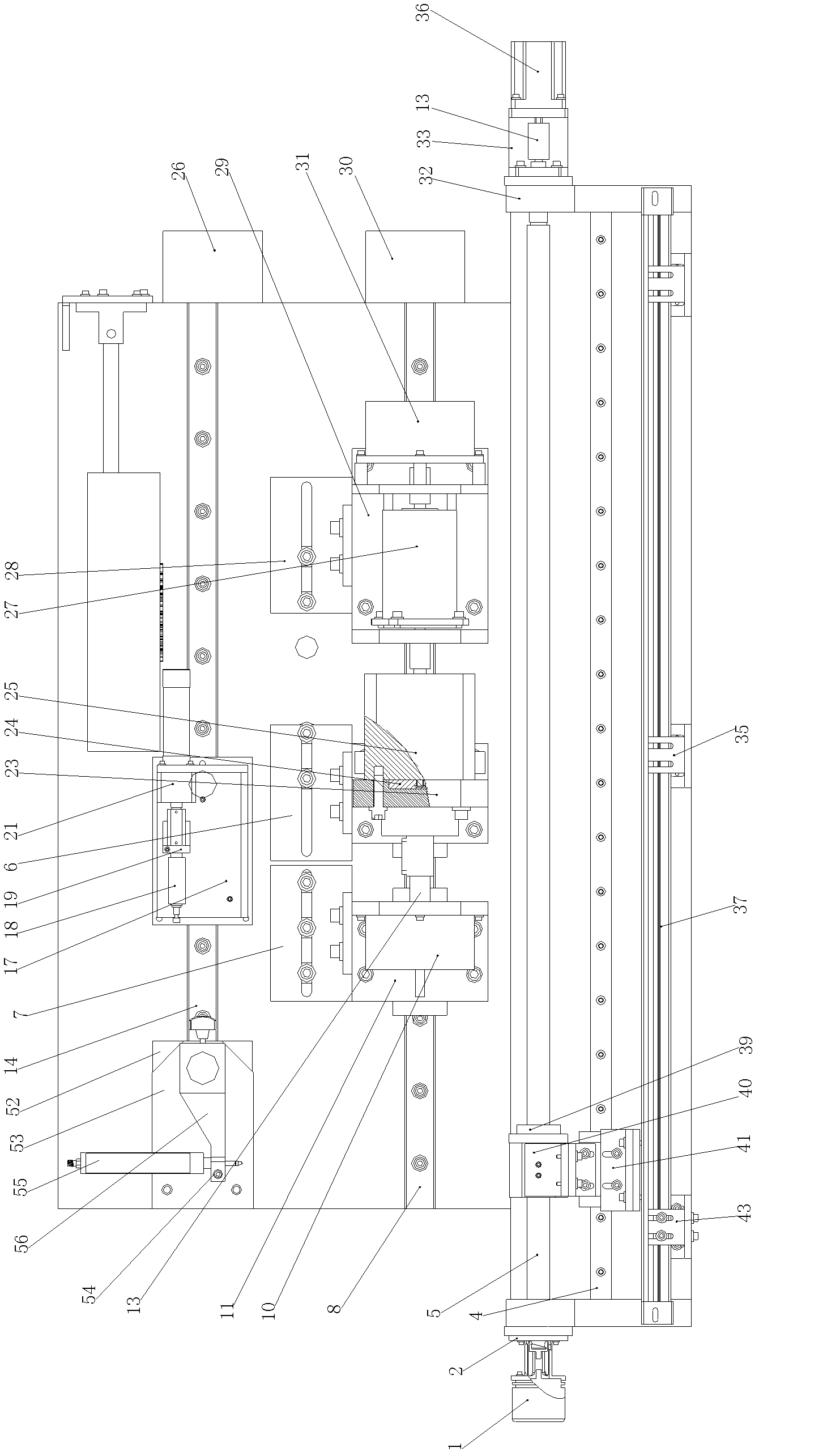
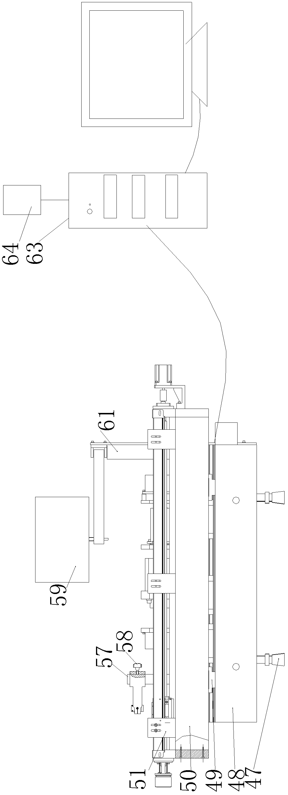
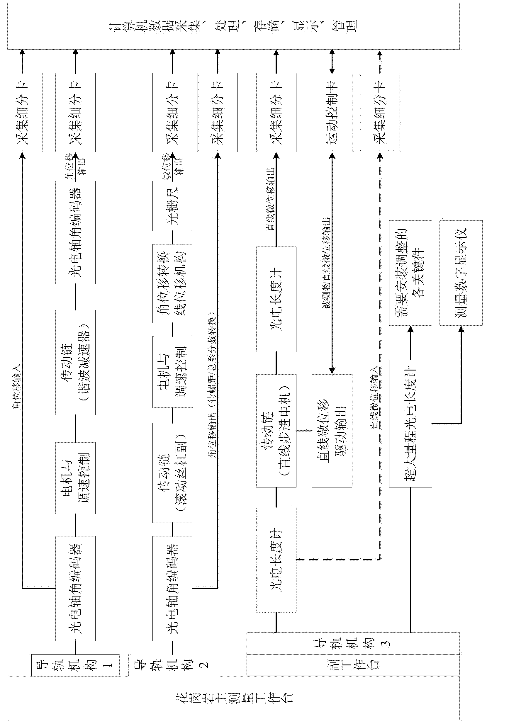
[0027] like figure 1 As shown, the precision transmission chain photoelectric measuring machine includes a measuring table, an angular displacement input and output grating measurement system, an angular displacement input and a linear displacement output grating measurement system, a linear micro-displacement input and an output grating measurement system, an installation error detection system and Measurement drive control system; three groups of precision linear guide rail mechanisms parallel to each other are installed on the base of the measurement workbench, and the angular displacement input and linear displacement output grating measurement system is installe...


PUM


Abstract

The invention discloses a photoelectric measuring machine for a precision transmission chain. The photoelectric measuring machine comprises a measuring worktable, an angular displacement input-output grating measuring system, an angular displacement input-linear displacement output grating measuring system, a linear micro-displacement input-output grating measuring system, an installation error detection system and a measurement drive control system, wherein, the base surface of the measuring worktable is provided with three groups of parallel precision linear guide rail mechanisms; the angular displacement input-linear displacement output grating measuring system is arranged on the first linear guide rail mechanism; the angular displacement input-output grating measuring system is arranged on the second linear guide rail mechanism; the linear micro-displacement input-output grating measuring system and the installation error detection system are arranged on the third linear guide rail mechanism; and the measurement drive control system is electrically connected with the angular displacement input-linear displacement output grating measuring system and the angular displacement input-output grating measuring system respectively. The photoelectric measuring machine for the precision transmission chain has the advantages of wide use and high measurement accuracy.

Description

technical field [0001] The invention relates to the field of photoelectric measurement, in particular to a precision transmission chain photoelectric measuring machine. Background technique [0002] Precision transmission chain photoelectric measuring machine (hereinafter referred to as "measuring machine") is a large-scale measuring equipment composed of light, machinery and electricity, which is used for precise measurement and analysis of precision transmission chain transmission errors. Especially suitable for high-end CNC machine tools and basic manufacturing equipment, automobiles, high-speed rail trains, aerospace, aviation, navigation precision instruments, automatic control systems, devices, measurement and testing instruments, equipment, robot joints, radar, optical tracking instruments, equipment, semiconductors, micro Measurement and analysis of dynamic transmission errors of various key transmission functional components, systems, and devices in electronic manuf...

Claims


Application Information

Patent Timeline
Patent Type & Authority Applications(China)
IPC IPC(8): G01M13/02
Inventor 许兴智李国洪高峰王晓张一钢史淑华
Owner 廊坊市莱格光电仪器有限公司
Why Eureka
Try Eureka