Machining method for hard-alloy turning tool

A technology of hard alloy and processing method, which is applied in the field of turning tool processing, can solve the problems of low efficiency and low processing accuracy, and achieve the effect of eliminating installation errors, high processing accuracy, and uniform variation of turning stress

Inactive Publication Date: 2016-05-11
平湖三川纺织染整股份有限公司
View PDF6 Cites 6 Cited by
  • Summary
  • Abstract
  • Description
  • Claims
  • Application Information

AI Technical Summary

Problems solved by technology

[0003] The problem to be solved by the present invention is to provide a processing method for hard alloy turning tools to solve the problems of low machining accuracy and low efficiency of existing hard alloy turning tools

Method used


Image

  • Machining method for hard-alloy turning tool
  • Machining method for hard-alloy turning tool
  • Machining method for hard-alloy turning tool

Examples


Embodiment Construction

[0013] Embodiments of the present invention are described in further detail below in conjunction with the accompanying drawings:

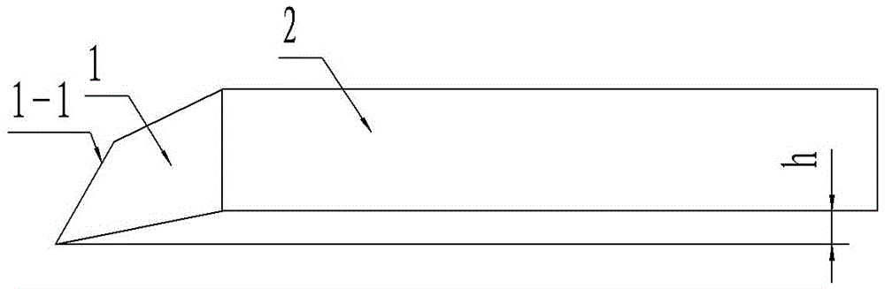
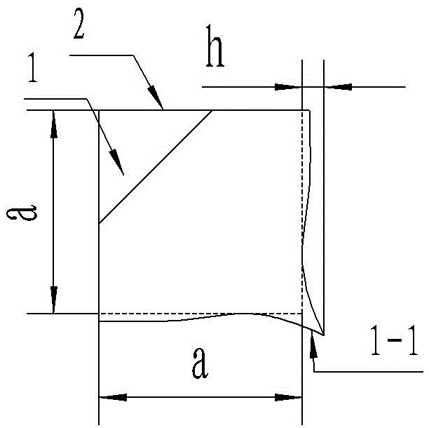
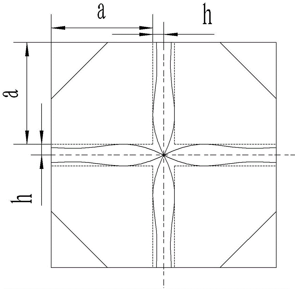
[0014] The processing method of this cemented carbide turning tool comprises processing a kind of cemented carbide turning tool, and this cemented carbide turning tool is as figure 1 , figure 2 , image 3 As shown, it includes a cutter bar 2 and a cutter head 1 connected to one end of the cutter bar 2, and the cutter bar 2 and the cutter head 1 are integrally formed. Therefore, the formation of installation errors is completely eliminated, and the error impact of the tool on the processed parts is reduced to the minimum. The cross-section of the knife rod part 2 is a square, and the width of each side is a. The cutter head 1 is inclined to an included angle of the cross-section of the cutter bar part 2, and the cutting edge section 1-1 of the cutter head part 1 is formed at the most pointed point, and the most pointed part of the cutting edge s...


PUM


Abstract

The invention discloses a machining method for a hard-alloy turning tool. The machining method comprises the step that the hard-alloy turning tool is machined. The hard-alloy turning tool comprises a tool bar part and a tool head part. The tool bar part and the tool head part are integrally formed. The cross section of the tool bar part is square. The tool head part inclines towards the cross section of the tool bar part by an included angle, and a cutting edge section of the tool head part is formed when the tool head part inclines to the sharpest position. The sharpest position of the cutting edge section protrudes from the side face of the tool bar part. The cutting edge section is recessed in the circular-arc shape before inclining to the sharpest position. The machining method comprises the following steps of A, sintering and B, linear cutting. Through the machining method, the problems of low machining precision and low efficiency of an existing hard-alloy turning tool can be solved.

Description

technical field [0001] The invention relates to the technical field of cemented carbide tool processing machinery, in particular to a processing method for a turning tool made of cemented carbide. Background technique [0002] Existing turning tools made of cemented carbide generally include a tool bar and a turning tool head. The tool bar and the turning tool head are two parts that are independently processed. The turning tool head is processed with hard alloy. , The turning head is installed on the tool bar, and the blade part of the turning tool head is generally wider than the width of the tool bar, so as to facilitate rough turning or fine turning of the workpiece. However, there will always be installation errors in the installation of the turning head and the tool holder, which will affect the machining accuracy of the finish car, and the cutting edge of the turning head is difficult to process and has a single shape, so it is difficult to process parts with complex ...

Claims


Application Information

Patent Timeline
Patent Type & Authority Applications(China)
IPC IPC(8): B23P15/30
CPCB23P15/30
Inventor 唐振荣
Owner 平湖三川纺织染整股份有限公司
Why Eureka
Try Eureka