Radar device

A radar device, a technology of sweeping frequency signals, applied in measurement devices, directional multi-channel systems using radio waves, instruments, etc., can solve the problem of long cycle time, inability to calculate distance, speed and angle, and large integral number N, etc. problems, to achieve the effect of improving signal detection performance, improving signal detection performance, and reducing the impact of errors

Inactive Publication Date: 2011-02-09
KK TOSHIBA
View PDF3 Cites 13 Cited by
  • Summary
  • Abstract
  • Description
  • Claims
  • Application Information

AI Technical Summary

Problems solved by technology

[0046] (1) In the case of combining an up-chirp and a down-chirp signal as a transmit-receive waveform, when multiple targets exist, the duality is difficult
In addition, the cycle time becomes longer because up-chirp and down-chirp signals need to be sent and received
[0047] (2) In the case of constraints on distance resolution or angular resolution, there are constraints on the separation performance of dense targets
[0048] (3) When the number of integrals N is small and the PRF is the same, the width of each frequency group of the beat frequency axis after the fast Fourier transform becomes larger and the frequency resolution deteriorates, and the distance and speed calculated based on the frequency The accuracy degrades
[0049] (4) In the case of performing complex Fourier transform on a real signal and extracting only the positive (or negative) frequency to extract the complex signal, when the correct sign of the target beat frequency is negative (or positive), the correct distance cannot be calculated, speed and angle
In this case, if there are constraints on the frequency band B and the sampling frequency PRF, the integral number N cannot be increased

Method used


Image

  • Radar device
  • Radar device
  • Radar device

Examples


Embodiment 1

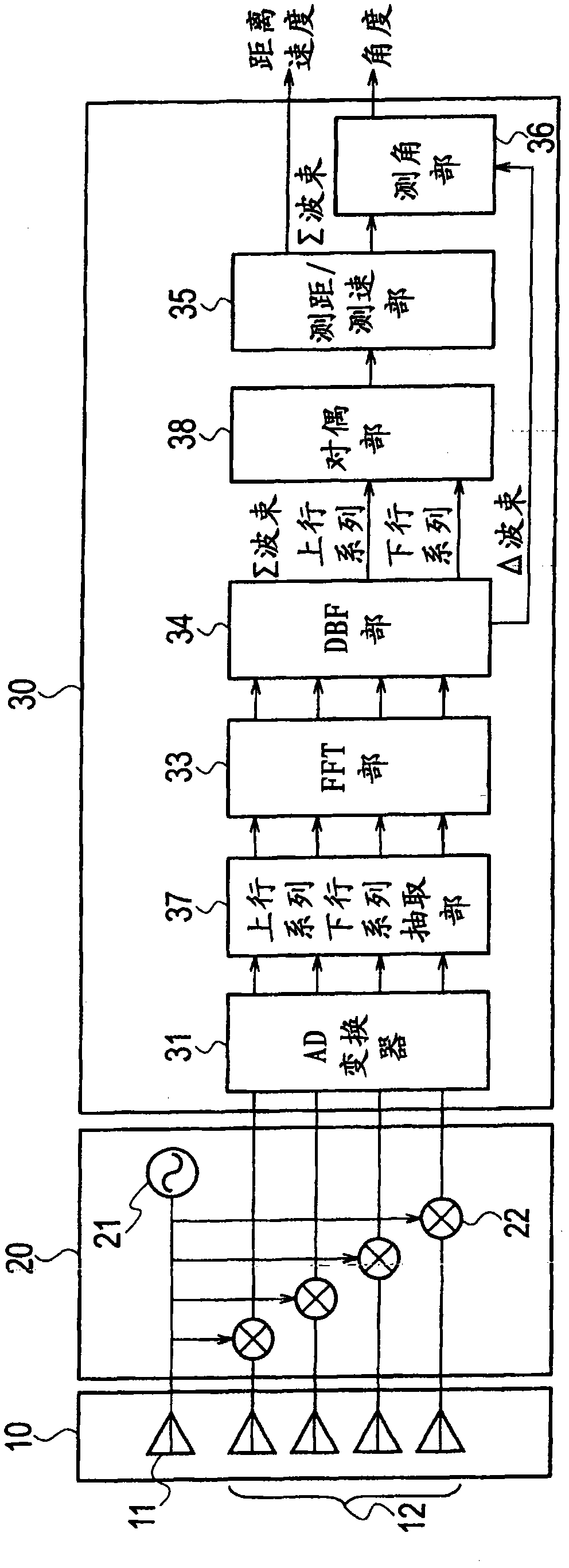
[0113] The radar device according to Embodiment 1 of the present invention adopts the MRAV (Measurement Range after measurement Velocity) method in which the distance is calculated after the velocity is calculated from the beat frequency. Figure 7 It is a system diagram showing the configuration of the radar device according to Embodiment 1 of the present invention. This radar device includes an antenna 10, a transceiver 20, and a signal processor 30a.

[0114] The antenna 10 is composed of an antenna radiating element 11 and a plurality of antenna receiving elements 12 . The antenna radiating element 11 converts a transmission signal as an electric signal from the transceiver 20 into an electric wave and sends it out to the outside. The plurality of antenna receiving elements 12 receive external radio waves, convert them into electrical signals, and send them to the transceiver 20 as received signals.

[0115] The transceiver 20 includes a transmitter 21 and a plurality of...

Embodiment 2

[0158] The radar device according to the second embodiment of the present invention employs a system in which a phase monopulse is combined with the MRAV system according to the above-mentioned first embodiment. The structure and the structure of the radar device involved in Embodiment 2 Figure 7 The configuration of the radar device according to the first embodiment shown is the same.

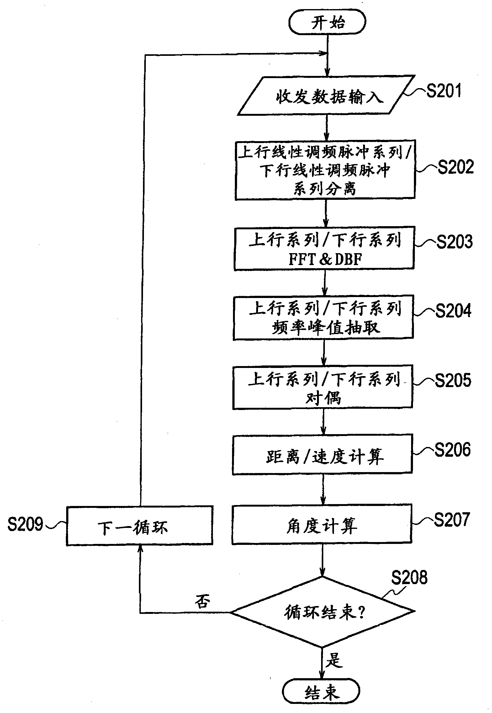
[0159] Figure 13This is a flowchart showing the operation of the radar device according to Embodiment 2 of the present invention, focusing on measurement processing for distance measurement, speed measurement, and angle measurement. In addition, for the Figure 8 The same or equivalent processing steps as the measurement processing related to the embodiment 1 shown in the flow chart of Figure 8 The same markup as used in . Hereinafter, description will be given mainly on parts different from the first embodiment.

[0160] In particular, when the PRF is the same and the number of sampli...

Embodiment 3

[0173] The radar device according to the third embodiment of the present invention uses an amplitude comparison monopulse instead of the phase monopulse of the radar device according to the second embodiment. The composition and the structure of the radar device involved in embodiment 3 Figure 7 The configuration of the radar device according to the first embodiment shown is the same. Hereinafter, the parts different from those in Embodiment 1 will be mainly described. In addition, the amplitude comparison monopulse (also referred to as amplitude monopulse) is described in "Supervisor Takashi Yoshida, 'Revised Radar Technology', Society of Electronics, Information and Communication, pp. 274-275 (1996)".

[0174] Using ∑(f) and ∑(f-1) and ∑(f+1) of the group before and after the frequency of the extracted target, compare the absolute value abs(∑(f-1)) and the absolute value abs(∑( f+1)), and the larger one is set as the absolute value abs(∑u).

[0175] Then, calculate the e...


PUM


Abstract

Provided is a device equipped with a transceiver (20) whereby sweep signals subjected to FMCW modulation is transmitted at least twice, an FFT unit (32) whereby at least two rounds of sweep signals received in response to transmission from the transceiver are subjected to fast Fourier transforms, and an MRAV processing unit (35a) whereby beat frequencies corresponding to each of the at least two rounds of sweeps by the transceiver are calculated on the basis of at least two rounds of sweep signals obtained by performing Fourier transforms in the FFT unit, whereby velocities are calculated on the basis of beat frequency differences and time differences that are calculated, and whereby distances are calculated on the basis of velocities and beat frequencies that are calculated, thereby making calculations of distances and velocities of a plurality of targets.

Description

technical field [0001] The present invention relates to a radar device for observing the distance and speed of a vehicle by FMCW (Frequency Modulated Continuous Wave) method. Background technique [0002] The FMCW system is known as a simple radar system for observing a vehicle running on a road with a radar device (see, for example, Non-Patent Document 1). When this FMCW system radar device is used, the distance and speed are unknown. Therefore, as a transmission and reception waveform, in general, two parameters are simultaneously calculated by combining an up chirp and a down chirp. [0003] However, on the beat frequency (beat frequency) axis of signals transmitted and received by up-chirp and down-chirp, there are differences even if the target frequency is the same. Therefore, correspondence can be achieved when only a single object exists. However, when there are a plurality of targets, there is a problem that it becomes difficult to pair up-chirp and down-chirp fo...

Claims


Application Information

Patent Timeline
Patent Type & Authority Applications(China)
IPC IPC(8): G01S13/44G01S7/02G01S13/34
CPCG01S13/44G01S2013/0263G01S13/584G01S3/74
Inventor 竹谷晋一川端一彰大须贺万城吉田卓司吉田大广丹羽雅人后藤秀人
Owner KK TOSHIBA
Why Eureka
Try Eureka