Solar energy electric heat utilization device and utilization method thereof

A solar energy and electric heating technology, applied in the field of solar energy utilization, can solve the problems of unreasonable structure, single solar energy utilization mode, and low efficiency, and achieve the effects of low manufacturing cost, simple structure principle, and improved efficiency

Inactive Publication Date: 2013-08-21
新昌县明盛纺织有限公司
View PDF6 Cites 13 Cited by
  • Summary
  • Abstract
  • Description
  • Claims
  • Application Information

AI Technical Summary

Problems solved by technology

[0006] In order to overcome the above-mentioned shortcomings, the present invention aims to provide a solar electric heating utilization device and its utilization method to

Method used


Image

  • Solar energy electric heat utilization device and utilization method thereof
  • Solar energy electric heat utilization device and utilization method thereof
  • Solar energy electric heat utilization device and utilization method thereof

Examples


Embodiment 1

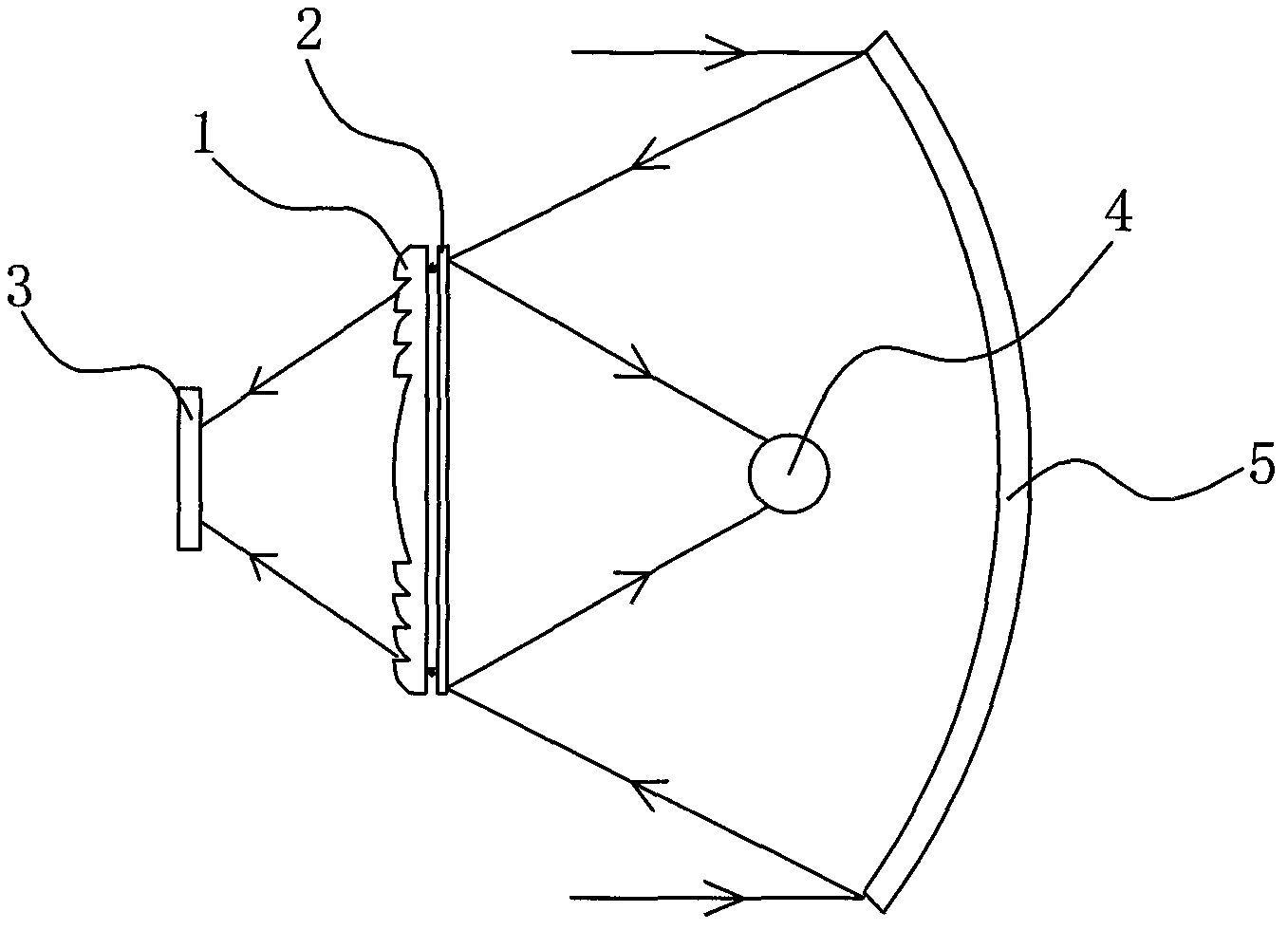
[0028] Embodiment one: if figure 1 As shown, the coated frequency divider is attached to the surface of one side of the Fresnel lens, and the coated frequency divider transmits short-wave light and reflects long-wave light. The coated frequency divider and the Fresnel lens are located between the photovoltaic cell and the heat receiver, and the coated frequency divider and the Fresnel lens receive the condensed beam of the condensing reflector. In the figure, the photovoltaic cell is located at the focus of the Fresnel lens, and the thermal receiver is located at the focus of the concentrated beam reflected by the coated frequency divider. The principle of this scheme is: the first time the sunlight is concentrated by the concentrating reflector to form a concentrating beam, and the concentrating beam is directed to the coated frequency dividing mirror and the Fresnel lens. Because the coated frequency-dividing mirror transmits short-wave light and reflects long-wave light, t...

Embodiment 2

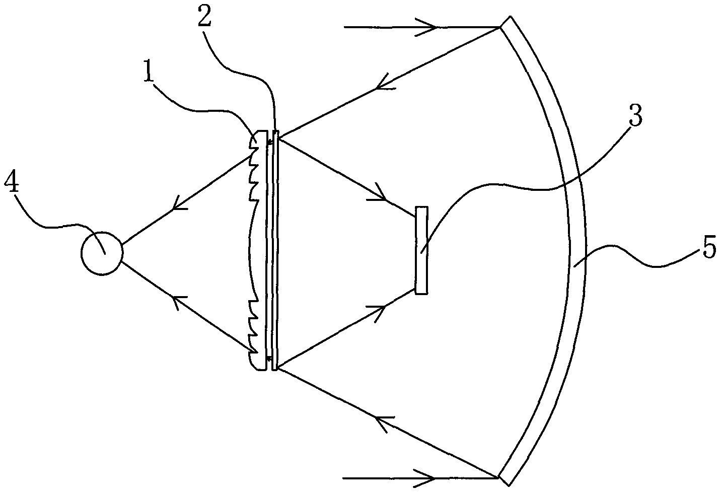
[0029] Embodiment two: if figure 2As shown, change the filter characteristics of the coated frequency-dividing mirror in Embodiment 1, set the coated frequency-dividing mirror to transmit long-wave light and reflect short-wave light, and exchange the positions of the photovoltaic cell and the heat receiver in Embodiment 1, That is, the thermal receiver is located at the focus of the Fresnel lens, and the photovoltaic cell is located at the focus of the concentrated beam reflected by the coated frequency divider. The principle of this scheme is: the first time the sunlight is concentrated by the concentrating reflector to form a concentrating beam, and the concentrating beam is directed to the coated frequency dividing mirror and the Fresnel lens. Because the coated frequency-dividing mirror transmits long-wave light and reflects short-wave light, the long-wave light in the concentrated beam will pass through the coated frequency-dividing mirror and be condensed twice by the F...


PUM


Abstract

The invention relates to a solar energy electric heat utilization device and a utilization method thereof and aims at solving the technical problems that structure is unreasonable, solar energy utilization method is single and efficiency is low of similar products in the prior art. The solar energy electric heat utilization device comprises a Fresnel lens, a coating film frequency division mirror, a photovoltaic cell, a heat receiver and a condensation reflector, and is characterized in that the Fresnel lens and the coating film frequency division mirror are arranged between the photovoltaic cell and the heat receiver, the Fresnel lens and the coating film frequency division mirror receive condensation light beams of the condensation reflector, one of the photovoltaic cell and the heat receiver are placed on a focusing portion of the Fresnel lens, and the other is placed on a focusing portion of the coating film frequency division mirror reflection condensation light beams. The solar energy electric heat utilization device is simple in structural principle, flexile in design, low in manufacturing cost, wide in application range, capable of distributing light utilization and heat utilization reasonably and effectively improving solar energy electric utilization efficiency and heat utilization efficiency, and is suitable for being used in solar energy utilization fields or structural improvements of similar products.

Description

technical field [0001] The invention relates to solar energy utilization, and relates to a solar electric heat utilization device and a utilization method thereof. Background technique [0002] At present, solar energy mainly has two aspects of heat utilization and electricity utilization. Thermal utilization refers to converting the light energy of sunlight into thermal energy, such as solar water heaters. Electricity utilization mainly includes photovoltaic power generation and photothermal power generation. The principle of photovoltaic power generation is the photovoltaic effect. When sunlight shines on photovoltaic cells, an electromotive force will be generated, which will be connected to a load to generate electricity. The principle of photothermal power generation is to use the absorber to absorb sunlight as a high-temperature heat source, and the thermal working medium absorbs the heat and enters the next power cycle. The common ones are steam turbines and gas turb...

Claims


Application Information

Patent Timeline
IPC IPC(8): H01L31/052F24J2/08F24J2/10F24S23/30F24S23/70H02S40/22
CPCY02E10/40Y02E10/52Y02E10/60
Inventor 杨浩仁
Owner 新昌县明盛纺织有限公司
Why Eureka
Try Eureka