Control device for machine tool

a technology for controlling devices and machine tools, applied in the direction of electric controllers, electric programme control, instruments, etc., can solve the problems of increasing equipment, power consumption, and difficulty in optimally reducing the total power consumption expended

Active Publication Date: 2010-10-21
FANUC LTD
View PDF6 Cites 12 Cited by
  • Summary
  • Abstract
  • Description
  • Claims
  • Application Information

AI Technical Summary

Benefits of technology

[0006]One aspect of the present invention provides a control device of a machine tool including a feed axis driving motor; a first power consumption calculating portion calculating power consumption of the feed axis driving motor; a second power consumption calculating portion calculating power consumption of equipment adapted to be operated by constant power; and a motor control portion determini...

Problems solved by technology

Therefore, in the device described in JP6-161535A, in which acceleration time of the servomotor is extended, it is difficult to optimally reduce total p...

Method used


Image

  • Control device for machine tool
  • Control device for machine tool
  • Control device for machine tool

Examples


Embodiment Construction

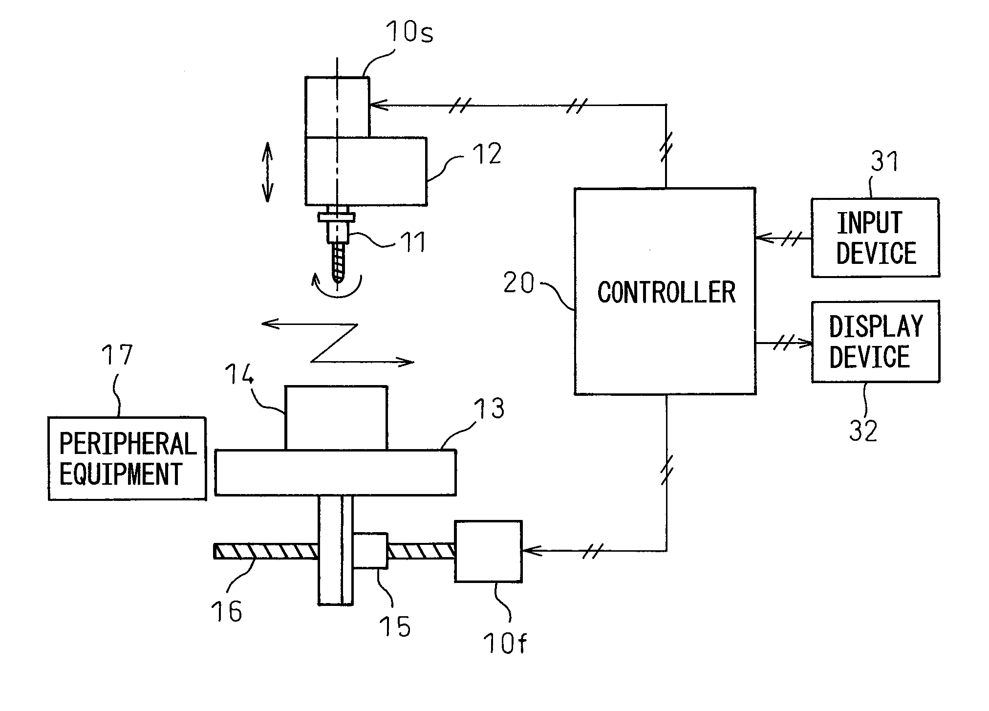
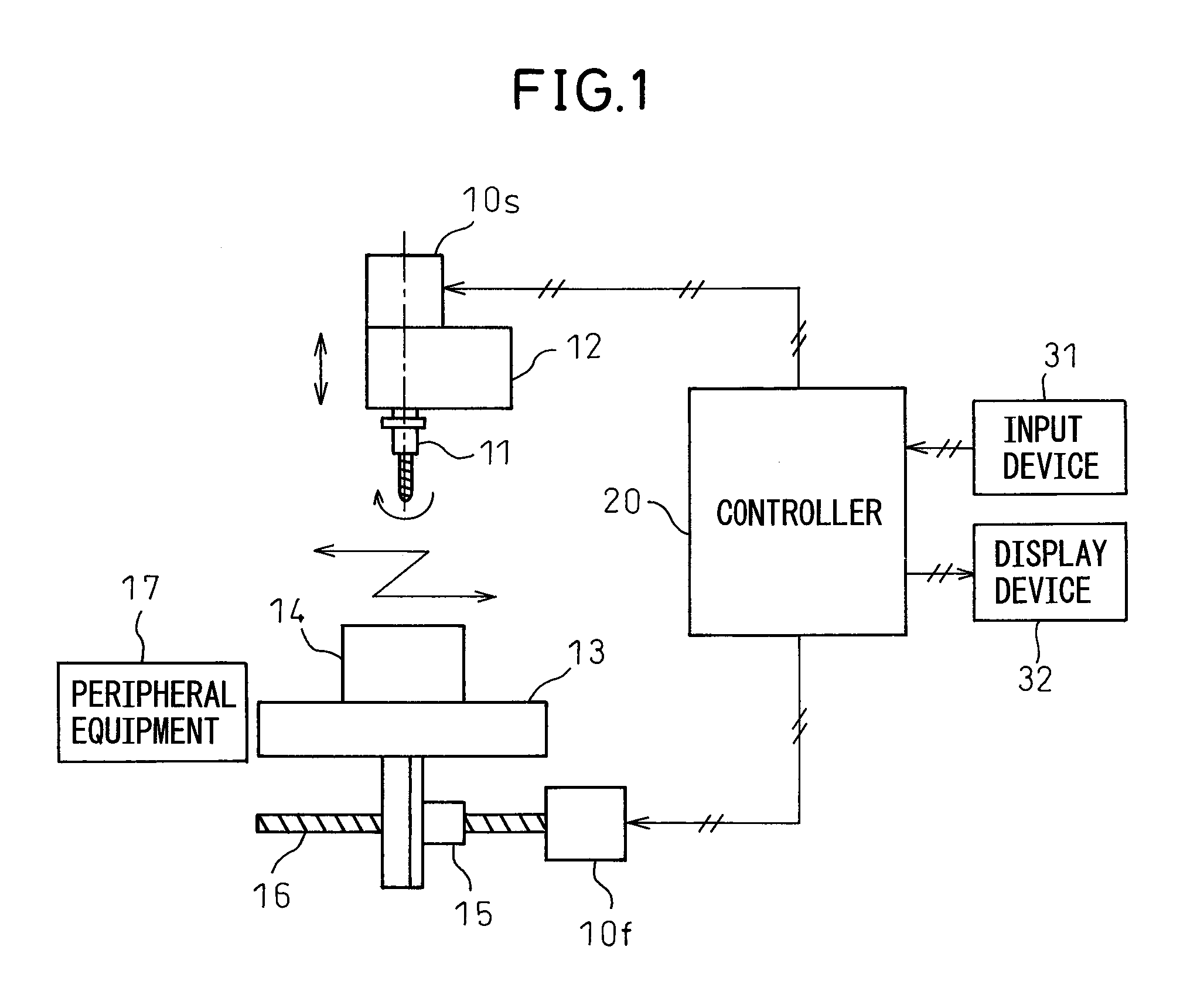
[0017]The embodiments of the present invention are described below, referring to FIGS. 1 to 8. FIG. 1 schematically illustrates the entire structure of a machine tool to which the embodiment of the invention is applied.

[0018]The machine tool shown in FIG. 1 is a so-called vertical-type machining center of which a spindle extends in the vertical direction. The spindle is rotated by a spindle motor 10s, and a tool 11 is rotated by the rotation of the spindle motor 10s. The tool 11 is a cutting tool such as an end mill, a cutter, or a drill, etc., or a grinding tool, and is detachably attached to a spindle head 12. A table 13 lies below the tool 11 and a workpiece 14 is fixed on the table 13.

[0019]A ball screw 16 is threadably engaged in the table 13 by a nut 15. The ball screw 16 is rotated by a feed axis motor 10f, so that the table 13 is moved in a horizontal direction (for example, X-Y directions). The same feeding mechanism (not shown) is also provided on the spindle side, so that...


PUM


Abstract

A control device for a machine tool including a feed axis driving motor; a first power consumption calculating portion calculating power consumption of the feed axis driving motor; a second power consumption calculating portion calculating power consumption of equipment adapted to be operated by constant power; and a motor control portion determining a target time constant correlated with at least one of acceleration time and deceleration time of the feed axis driving motor, based on a summation of the power consumption calculated by the first power consumption calculating portion and the power consumption calculated by the second power consumption calculating portion, and controlling the feed axis driving motor based on the target time constant.

Description

BACKGROUND OF THE INVENTION[0001]1. Field of the Invention[0002]The present invention relates to a control device for controlling a machine tool, such as a machining center, etc.[0003]2. Description of the Related Art[0004]A device for reducing power consumption during machining of a workpiece is wellknown. The device described in Japanese Unexamined Patent Publication (kokai) No. 6-161535 (JP6-161535A) is configured to extend acceleration time of an axis-feed servomotor so as to reduce a maximum value of required current, and thus reduces power consumption.[0005]In such a machine tool, not only the axis-feed motor but also equipment which operate at a constant power, such as an oil pump for supplying cutting oil, etc., is driven at the same time during machining of a workpiece. Therefore, in the device described in JP6-161535A, in which acceleration time of the servomotor is extended, it is difficult to optimally reduce total power consumption expended by the machine tool, because ...

Claims


Application Information

Patent Timeline
IPC IPC(8): G05B11/01B23Q15/00G05B19/416H02P29/00
CPCG05B2219/34314G05B19/416
Inventor IWASHITA, YASUSUKEOKITA, TADASHITEZUKA, JUNICHI
Owner FANUC LTD
Why Eureka
Try Eureka