Winding structure for a transformer and winding

Inactive Publication Date: 2010-10-21
DELTA ELECTRONICS INC
View PDF6 Cites 16 Cited by
  • Summary
  • Abstract
  • Description
  • Claims
  • Application Information

AI Technical Summary

Benefits of technology

[0010]To solve the aforesaid problems, an objective of the present invention is to provide a winding structure for use in a transformer, which facilitates the production of the winding as a whole and features desirable stability after being manufactured. Accordingly, the problems of short circuits, failure in electrical connection between winding disks and damage to insulation parts are avoided.
[0012]As described above, the main components of the winding structure of the present invention are formed separately and then combined together by means of the connecting part. As a result, the conductive components and the insulation components may be stamped separately, thereby preventing the generation of burrs and fractures at the junctures during the stamping process as in the prior art. Furthermore, as compared to the prior art in which an insulation adhesive tape is attached on the winding disks, the insulation disk of the present invention may be made of a material that can endure a high temperature, thereby providing more flexibility in use. Therefore, the problems confronted by the prior art are eliminated in the winding structure of the present invention.

Problems solved by technology

Consequently, electrical functionalities originally designed for the structure may fail to be satisfied.
Furthermore, during the folding process, a fracture may occur at junctures where the first winding disk 11 and the second winding disk 12 join with each other due to the application of an undue force, causing failure of electrical connection between the first winding disk 11 and the second winding disk 12 and consequently making it impossible for the winding structure 1 to function properly.
As described above, defects tend to occur in the manufacturing process of the winding structure of conventional transformers, resulting in short circuits, failure in electrical connections and damage to insulation parts.

Method used


Image

  • Winding structure for a transformer and winding
  • Winding structure for a transformer and winding
  • Winding structure for a transformer and winding

Examples


Embodiment Construction

[0021]In the following description, a winding structure of the present invention will be explained with reference to embodiments thereof. However, it shall be appreciated that these embodiments are not intended to limit the present invention to any specific environment, applications or particular implementations described in these embodiments. Therefore, description of these embodiments is only for purpose of illustration rather than to limit the present invention.

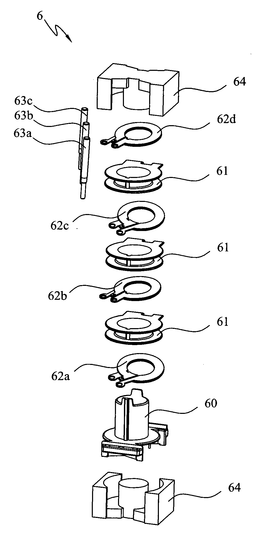
[0022]As shown in FIG. 5, an embodiment of the present invention is a winding structure 5, which comprises a first conductive disk 2, a second conductive disk 3, an insulation disk 4 and a connecting part 52.

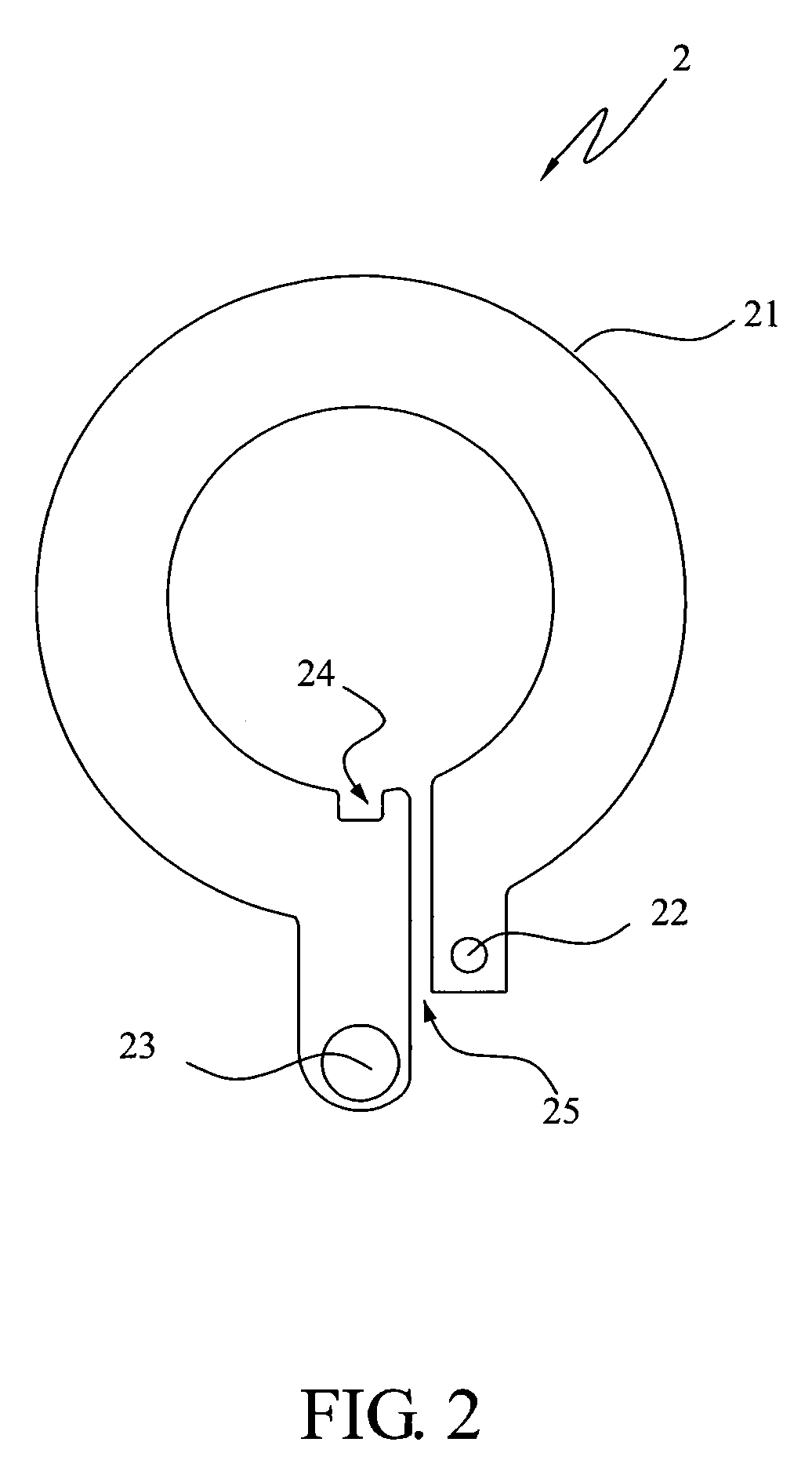
[0023]The first conductive disk 2 is substantially of a circular shape having a first open circular portion 21, a first connection hole 22, a first wiring terminal 23 and a notch 24. The first open circular portion 21 is formed with a first opening 25, a schematic view of which is shown in FIG. 2. In other words, the f...


PUM


Abstract

A winding structure adapted for a transformer and a winding are provided. The winding structure comprises a first conductive disk, a second conductive disk, a connecting part, and an insulation disk which is disposed between the first conductive disk and the second conductive disk. The first conductive disk has a first open circular portion and a first connection hole, the second conductive disk has a second open circular portion and a second connection hole and the isolation disk has a third connection hole. The first conductive disk, the second conductive disk and the insulation disk are combined by the connecting part through the first connection hole, the second connection hole and the third connection hole, and the first conductive disk is electrically connected with the second conductive disk therefore.

Description

[0001]This application claims priority to Taiwan Patent Application No. 098206421 filed on Apr. 17, 2009, the disclosures of which are incorporated herein by reference in their entirety.CROSS-REFERENCES TO RELATED APPLICATIONS[0002]Not applicable.BACKGROUND OF THE INVENTION[0003]1. Field of the Invention[0004]The present invention relates to a winding structure for use in a transformer.[0005]2. Descriptions of the Related Art[0006]Because transformers can transform voltages, change impedances and separate circuits, they are often used in a wide variety of electronic products. Meanwhile, windings are known as essential components for voltage transformation in transformers. Nowadays, a number of structural improvements on transformers have been made depending on various usage demands.[0007]FIG. 1 illustrates a winding structure 1 commonly found in conventional transformers is shown therein. The winding structure 1 is mostly formed integrally and is structurally divided into a first wi...

Claims


Application Information

Patent Timeline
IPC IPC(8): H01F27/28
CPCH01F27/2852H01F27/303H01F2027/2857H01F27/325H01F27/323
Inventor XIONG, BLUEZHOU, JACKLIU, JINGKUNG, C.S.
Owner DELTA ELECTRONICS INC
Why Eureka
Try Eureka