
Image display method

a display method and image technology, applied in the field of image display methods, can solve the problems of reducing the display quality, unable to keep the visual effect of an original image, and the most power-consuming component of the light source module in the lcd, so as to reduce the power consumption of the display panel effectively, increase the cost of software/hardware, and be environmentally friendly.

Inactive Publication Date: 2010-10-21
WINTEK CORP
View PDF11 Cites 14 Cited by
  • Summary
  • Abstract
  • Description
  • Claims
  • Application Information

AI Technical Summary

Benefits of technology

[0007]Accordingly, the present invention is directed to an image display method, wherein a backlight of a display panel is adjusted according to an external light, brightness factors of an original image are corrected according to the adjustment of the backlight, and the original image is reset by using the corrected brightness factors and original color factors. Accordingly, the problem of image contrast distortion caused by backlight adjustment can be resolved without affecting the image visual effect or increasing the hardware / software cost.
[0011]As described above, in the present invention, a backlight of a display panel is adaptively adjusted according to a backlight adjustment factor related to the intensity value of an external light and the brightness of an original image, so as to reduce the power consumption of the display panel effectively. Moreover, in the present invention, brightness factors in the original image are corrected according to the adjustment of the backlight, and the original image is reset according to the corrected brightness factors, so that the problem of image contrast distortion caused by backlight adjustment can be effectively resolved without affecting the image visual effect or increasing the software / hardware cost. Furthermore, in the present invention, a solar cell is adopted and the power required by a display panel is supplied by an external light source, so that the display panel is made more environment-friendly.

Problems solved by technology

The light source module needs to emit light constantly once the LCD is turned on, and accordingly the light source module is the most power-consuming component in the LCD.
However, this technique reduces the display quality and cannot keep the visual effect of an original image.
However, this technique requires different designs regarding different devices and takes up too much memory space, and as a result, causes both hardware cost and software cost to be increased.

Method used


Image

  • Image display method
  • Image display method
  • Image display method

Examples


first embodiment

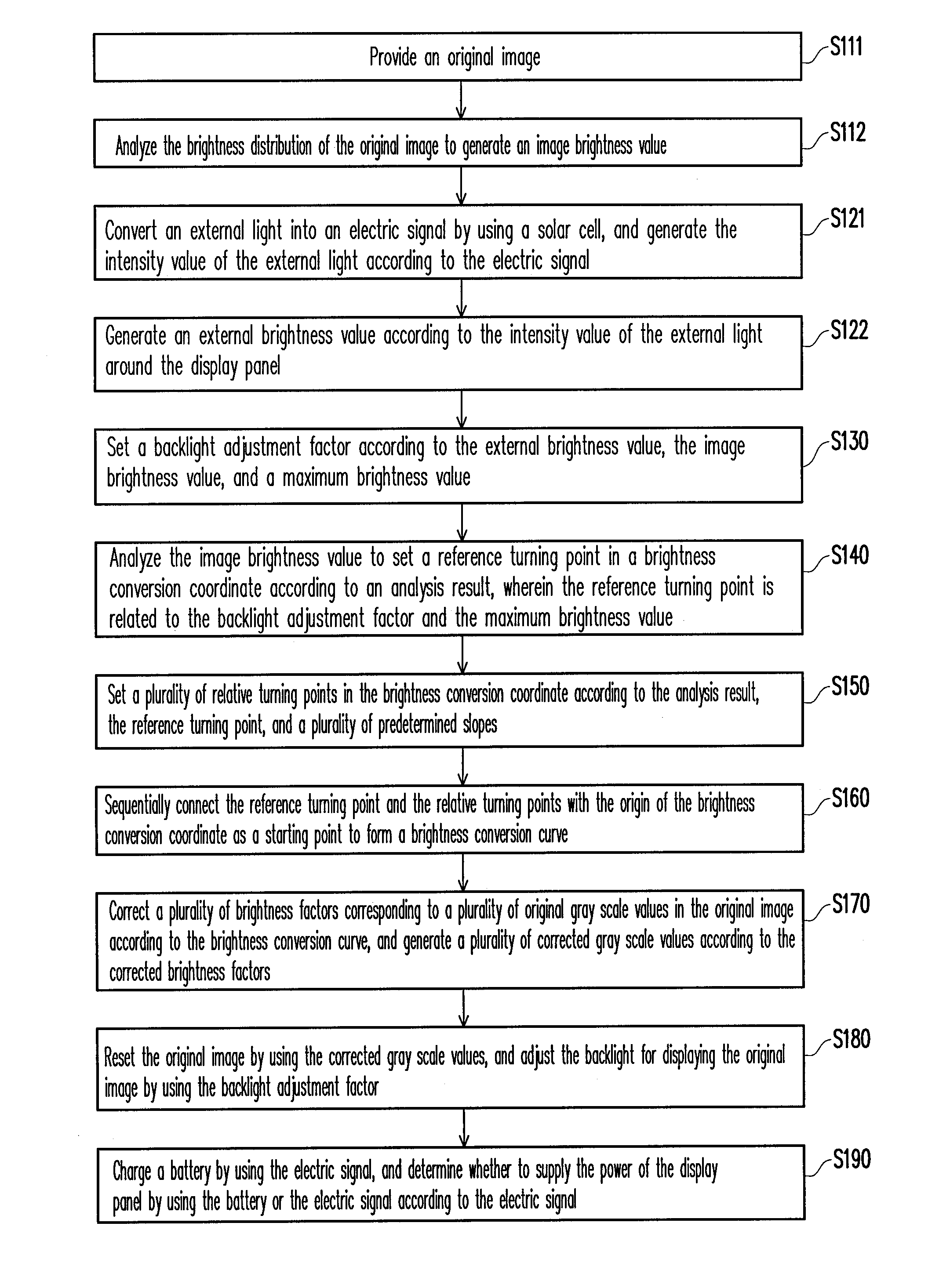
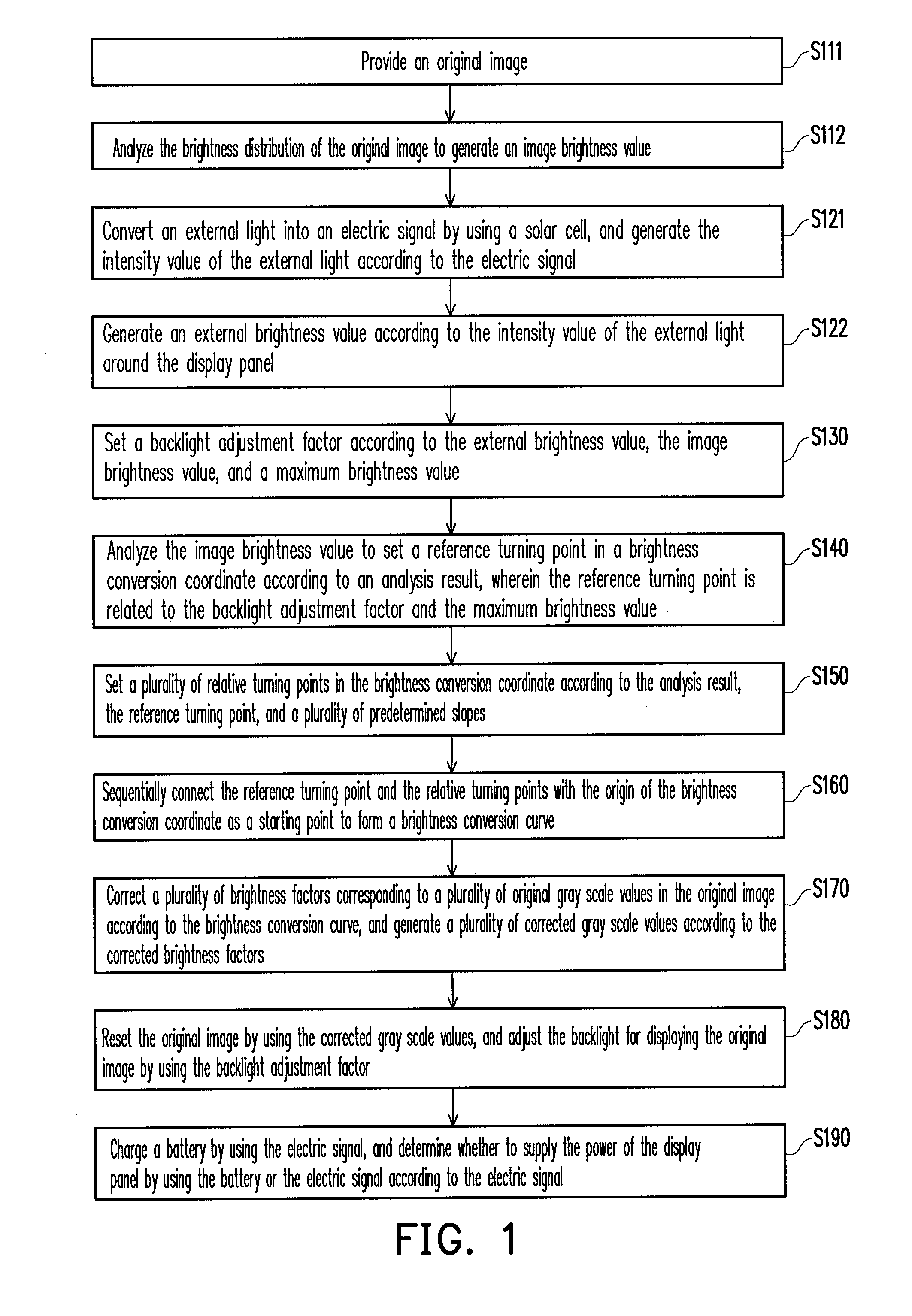
[0033]FIG. 1 is a flowchart of the first embodiment of the present invention, and which is adaptable to a transmissive display panel. In step S111, an original image is provided. Then, in step S112, the brightness distribution of the original image is analyzed to generate an image brightness value.

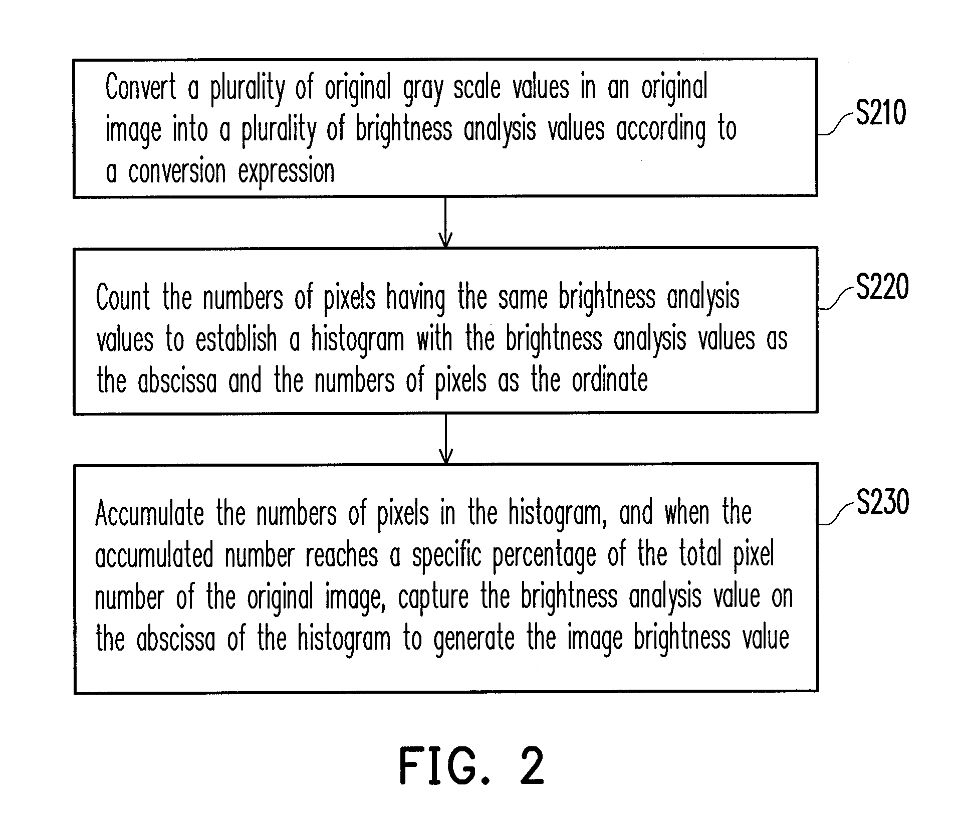
[0034]Refering to FIG. 2, in step S210, a plurality of original gray scale values in the original image is converted into a plurality of brightness analysis values according to a conversion expression. For example, if an ith brightness analysis value is denoted as BTi, the three sub gray scale values in the ith original gray scale value are respectively denoted as ri, gi, and bi, a maximum brightness value is denoted as aplmax, a maximum gray scale value is denoted as grmax, and i is an integer greater than 0, each of the original gray scale values can be converted into the corresponding brightness analysis value through the following conversion expression (1):

BTi=(0.299×ri+0.578×gi+0.114×...

second embodiment

[0074]FIG. 14 is a flowchart of an image display method according to the second embodiment of the present invention. The image display method in the present embodiment is adaptable to a transflective display panel. Referring to FIG. 1 and FIG. 14, the difference between the second embodiment and the first embodiment falls on the detailed procedures of the steps S122′ and S130′.

[0075]To be specific, similar to the first embodiment, an original image is provided in step S111 and analyzed in step S112 to obtain an image brightness value related to the brightness of the original image. Besides, in the present embodiment, in steps S121 and S122′, an external brightness value related to the intensity value of an external light is further generated by using an electric signal converted by a solar cell. In step S130′, a backlight adjustment factor is set according to the external brightness value, the image brightness value, and a maximum brightness value.

[0076]In the present embodiment, a ...

third embodiment

[0084]FIG. 16 is a flowchart of an image display method according to the third embodiment of the present invention. The image display method in the present embodiment is adaptable to a transmissive display panel or a transflective display panel. Referring to FIG. 1 and FIG. 16, the difference between the third embodiment and the first embodiment falls on the new steps S1601˜S1603 and the detailed procedures of the steps S122″ and S130″.

[0085]To be specific, in the present embodiment, similar to the first embodiment, an original image is provided in step S111 and analyzed in step S112 to obtain an image brightness value related to the brightness of the original image. Besides, in steps S121 and S122″, an external brightness value related to the intensity value of an external light is further generated by using an electric signal converted by a solar cell. In step S130″, a backlight adjustment factor is set by using the external brightness value, the image brightness value, and a maxi...


PUM


Abstract

An image display method including following steps is provided. A backlight of a display panel is adaptively adjusted according to a backlight adjustment factor related to the intensity value of an external light and the brightness of an original image. Brightness factors of the original image are corrected according to the adjustment of the backlight, and the original image is reset by using the corrected brightness factors and original color factors. Thereby, the problem of image distortion caused by backlight adjustment can be reduced.

Description

CROSS-REFERENCE TO RELATED APPLICATION[0001]This application claims the priority benefit of Taiwan application serial no. 98113018, filed on Apr. 20, 2009. The entirety of the above-mentioned patent application is hereby incorporated by reference herein and made a part of specification.BACKGROUND OF THE INVENTION[0002]1. Field of the Invention[0003]The present invention generally relates to an image display method, and more particularly, to an image display method which can reset an original image according to the adjustment of a backlight.[0004]2. Description of Related Art[0005]A LCD includes a LCD panel and a light source module. The LCD panel itself does not emit light, and therefore the light source module has to be disposed for providing a surface light source to allow the LCD panel to display images. The light source module needs to emit light constantly once the LCD is turned on, and accordingly the light source module is the most power-consuming component in the LCD. Genera...

Claims


Application Information

Patent Timeline
IPC IPC(8): G09G5/02
CPCG09G3/3406G09G3/3611G09G2320/0646G09G2360/16G09G2330/021G09G2360/144G09G2330/02
Inventor HSU, CHING-FULAI, CHIH-CHANGLIAO, SHIAO-HUICHANG, TING-YU
Owner WINTEK CORP
Learn More