Variable power optical system, imaging device, and digital device

Active Publication Date: 2010-10-21
KONICA MINOLTA OPTO
View PDF3 Cites 33 Cited by
  • Summary
  • Abstract
  • Description
  • Claims
  • Application Information

AI Technical Summary

Benefits of technology

[0042]According to the present invention, in a variable power optical system having a first lens group having a negative optical power, a second lens group having a positive optical power, and a third lens group having negative optical power, the first lens group is constituted from a single negative lens, and is fixed during power variation, the third lens group is constituted to have, not only at least one aspherical surface, but also a front group having a negative optical power and a rear group having a positive optical power. Becaus

Problems solved by technology

However, in the variable power optical system described in Patent Document 1, although making compact the variable power optical system has been achieved by making one group fixed, the system is extremely wide-angle, even the distortion is relatively large, and also the power ratio is small.
Further, in the variable power optical system described in Patent Document 2, the corrections of axial chromatic aberration and chromatic aberration of magnification are not sufficient, and it is difficult to satisfy the high number of pixels of imaging devices of recent years.
Further, in the variable power optical system described in Patent Document 3, since the system is too wide-angle, it is not suitable for standard photography but is for special applications.
In addition, the distortion at the wide angle end is too large being −40%, the power ratio is small, and also the tele-centric characteristics are bad.
Further, in the variable power optical system described in Patent Document 4, the power ratio is small, and also the tele-centric characteristics are bad.
Further, in the variable power optical system described in Patent Document 5, the size reduction is not sufficient in both the effective diameter and the overall length.
Further, in the variable power optical sys

Method used


Image

  • Variable power optical system, imaging device, and digital device
  • Variable power optical system, imaging device, and digital device
  • Variable power optical system, imaging device, and digital device

Examples


implementation examples

Implementation Example 1

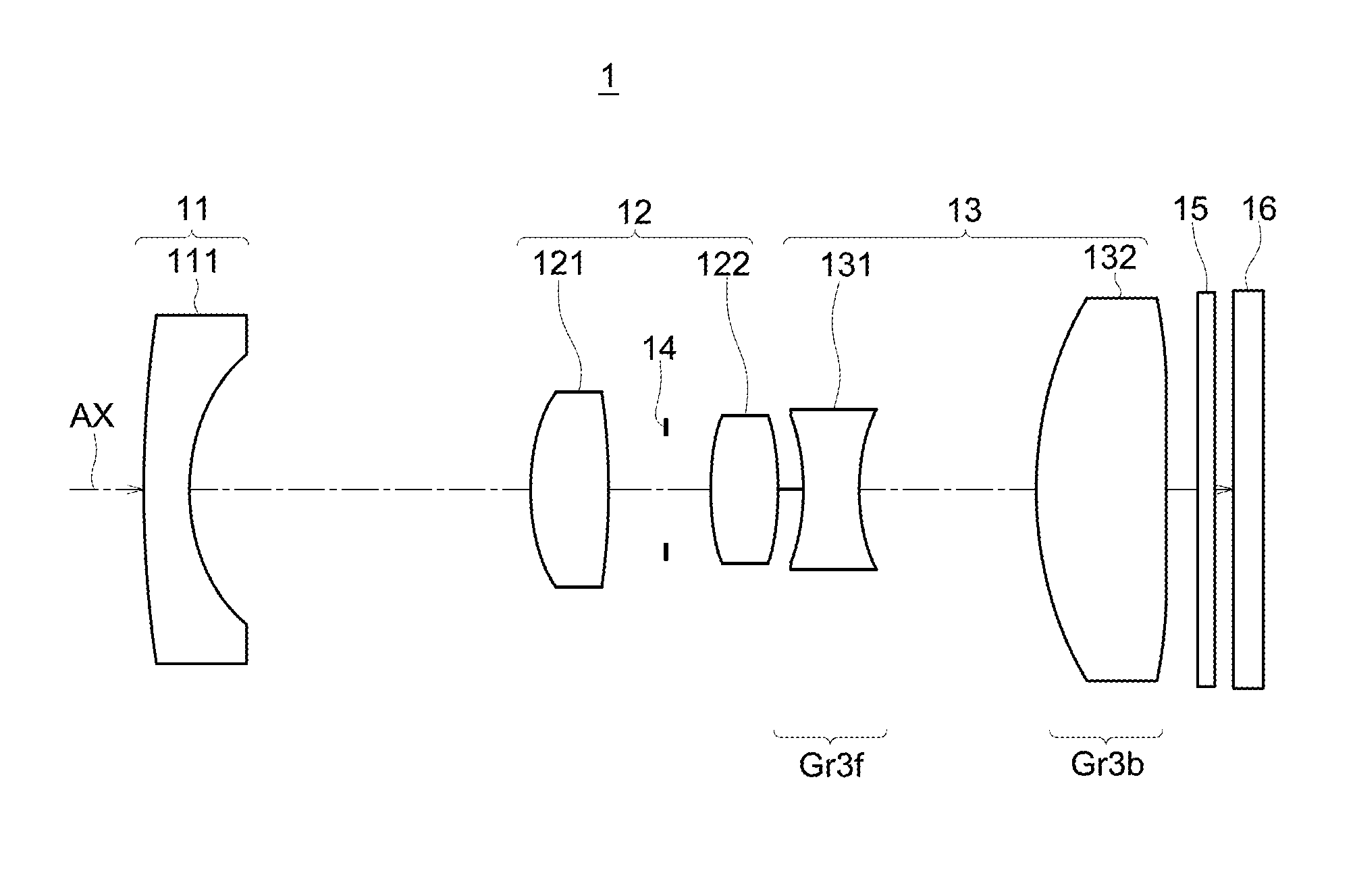
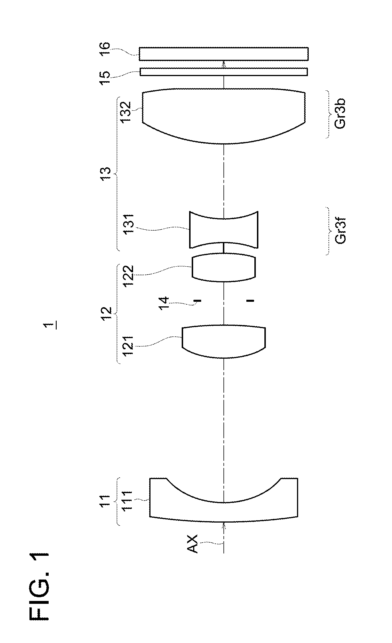
[0187]FIG. 4 is a cross-sectional view diagram showing an example of the arrangement of lens groups in a variable power optical system according to the Implementation Example 1. FIG. 4A shows the case at the wide angle end, FIG. 4B shows the case at the mid point, and FIG. 4C shows the case at the telephoto end. Further, similar cases are also shown in A, B, and C of FIG. 6, FIG. 8, FIG. 10, FIG. 12, FIG. 14, FIG. 16, FIG. 18, FIG. 20, FIG. 22, and FIG. 24 which are the cross-sectional view diagrams showing examples of the arrangement of lens groups in the variable power optical systems 1B to 1K according to the Implementation Example 2 through Implementation Example 11 which are described later.

[0188]FIG. 5 is a diagram showing the form of movement of the different lens groups during power variation of a variable power optical system of the Implementation Example 1. In this figure, A shows the case at the wide angle end described above, B shows the case at t...

implementation example 2

[0213]FIG. 6 is a cross-sectional view diagram showing an example of the arrangement of lens groups in a variable power optical system according to the Implementation Example 2. FIG. 7 is a diagram showing the form of movement of the different lens groups during power variation of a variable power optical system of the Implementation Example 2. FIG. 27 is an aberration diagram of a variable power optical system of the Implementation Example 2.

[0214]The variable power optical system 1B of the Implementation Example 2, as is shown in FIG. 6, is a negative-positive-negative three component zoom construction with the lens groups (Gr1, Gr2, and Gr3) arranged in sequence from the object side towards the image side to have, a first lens group (Gr1) having on the whole a negative optical power, a second lens group (Gr2) having on the whole a positive optical power, and a third lens group (Gr3) including an aperture opening ST and having on the whole a negative optical power, and at the time...

implementation example 3

[0224]FIG. 8 is a cross-sectional view diagram showing an example of the arrangement of lens groups in a variable power optical system according to the Implementation Example 3. FIG. 9 is a diagram showing the form of movement of the different lens groups during power variation of a variable power optical system of the Implementation Example 3. FIG. 28 is an aberration diagram of a variable power optical system of the Implementation Example 3.

[0225]The variable power optical system 1C of the Implementation Example 3, as is shown in FIG. 8, is a negative-positive-negative three component zoom construction with the lens groups (Gr1, Gr2, and Gr3) arranged in sequence from the object side towards the image side to have, a first lens group (Gr1) having on the whole a negative optical power, a second lens group (Gr2) including an aperture opening ST and having on the whole a positive optical power, and a third lens group (Gr3) having on the whole a negative optical power, and at the time...


PUM


Abstract

A variable power optical system (1) comprises a first lens group (11) having a negative optical power, a second lens group (12) having a positive optical power, and a third lens group (13). The first to third lens groups are arranged in order from the object side to the image side. The first lens group (11) is composed of one negative lens (111) and is fixed in variable power. The third lens group (13) includes at least one aspherical surface. When the third lens group is divided into a front group and a rear group with the largest air space in the third group, the front group has a negative optical power, and the rear group has a positive optical power.

Description

TECHNICAL FIELD OF THE INVENTION[0001]The present invention relates to variable power optical systems, and in particular, to variable power optical systems that can be made compact. Further, the present invention relates to imaging devices provided with such variable power optical systems, and to digital devices in which such imaging devices are installed.TECHNICAL BACKGROUND OF THE INVENTION[0002]In recent years, the proliferation is striking of portable terminals provided with communication functions such as mobile telephones, PDA (Personal Digital Assistants), etc., that are portable, and very often imaging devices capable of still image photography or moving image photography such as, for example, digital still cameras or digital movie cameras, etc., are installed in these devices. The restrictions of size (dimensions) and cost on the imaging devices installed in these devices, normally, are very severe. Because of this, compared to the so called independent digital camera, smal...

Claims


Application Information

Patent Timeline
IPC IPC(8): H04N5/225G02B15/14
CPCG02B15/177G02B7/008G02B15/143507G02B15/143503
Inventor FUKUTA, YASUNARI
Owner KONICA MINOLTA OPTO
Why Eureka
Try Eureka