
Turbine Arrangement

Inactive Publication Date: 2010-10-21
FLUMILL
View PDF15 Cites 12 Cited by
  • Summary
  • Abstract
  • Description
  • Claims
  • Application Information

AI Technical Summary

Benefits of technology

[0011]The adjacent screw turbines may thereby be spaced apart by a center distance which is smaller than the diameter of the screw turbines, which reduces the flow opening between the screw turbines. This condition provides for improved utilization of the flowing water. The two screw turbines rotate in opposite directions and are therefore affected symmetrically by the flowing water.
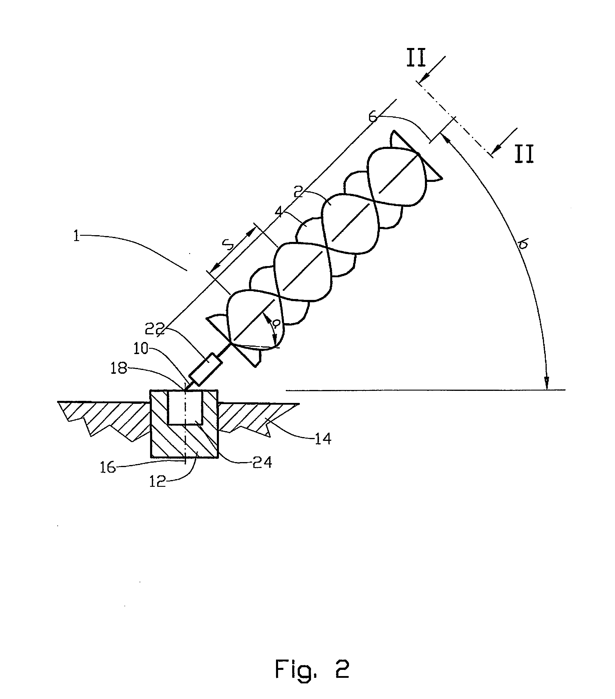
[0017]It is possible to maintain a desired angle between the screw turbine and the horizontal plane by controlling the power output of the power machine, wherein a reduced power output will have the effect of the buoyancy, which seeks to pivot the turbine arrangement into a vertical position, pivoting the turbine arrangement into a larger angle relative to the horizontal plane.
[0021]In relation to the prior art, the turbine arrangement according to the invention provides a substantial simplification of the task of extracting energy from flowing sea water. The construction is considerably simpler because the bottom mount is not subjected to bending moments. The turbine arrangement according to the invention is also well suited for use in relatively shallow regions and could thereby conceivably also be used in river courses.

Problems solved by technology

However, it has turned out to be connected with considerable challenges to extract energy of some significance from tidal flows.
Some prior art tower structures also project above the sea surface, which may have a disfiguring effect and be a hindrance to shipping.

Method used


Image

  • Turbine Arrangement
  • Turbine Arrangement
  • Turbine Arrangement

Examples


Embodiment Construction

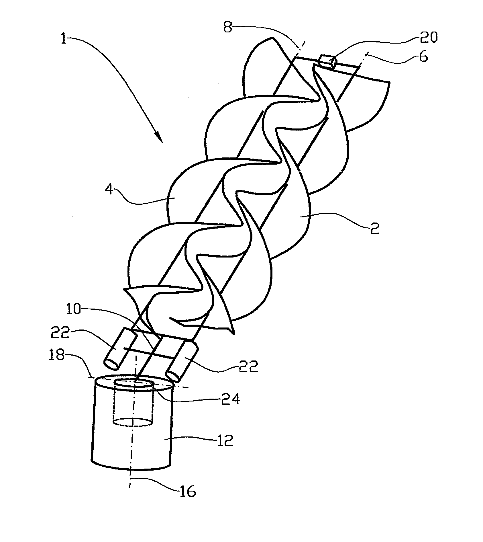
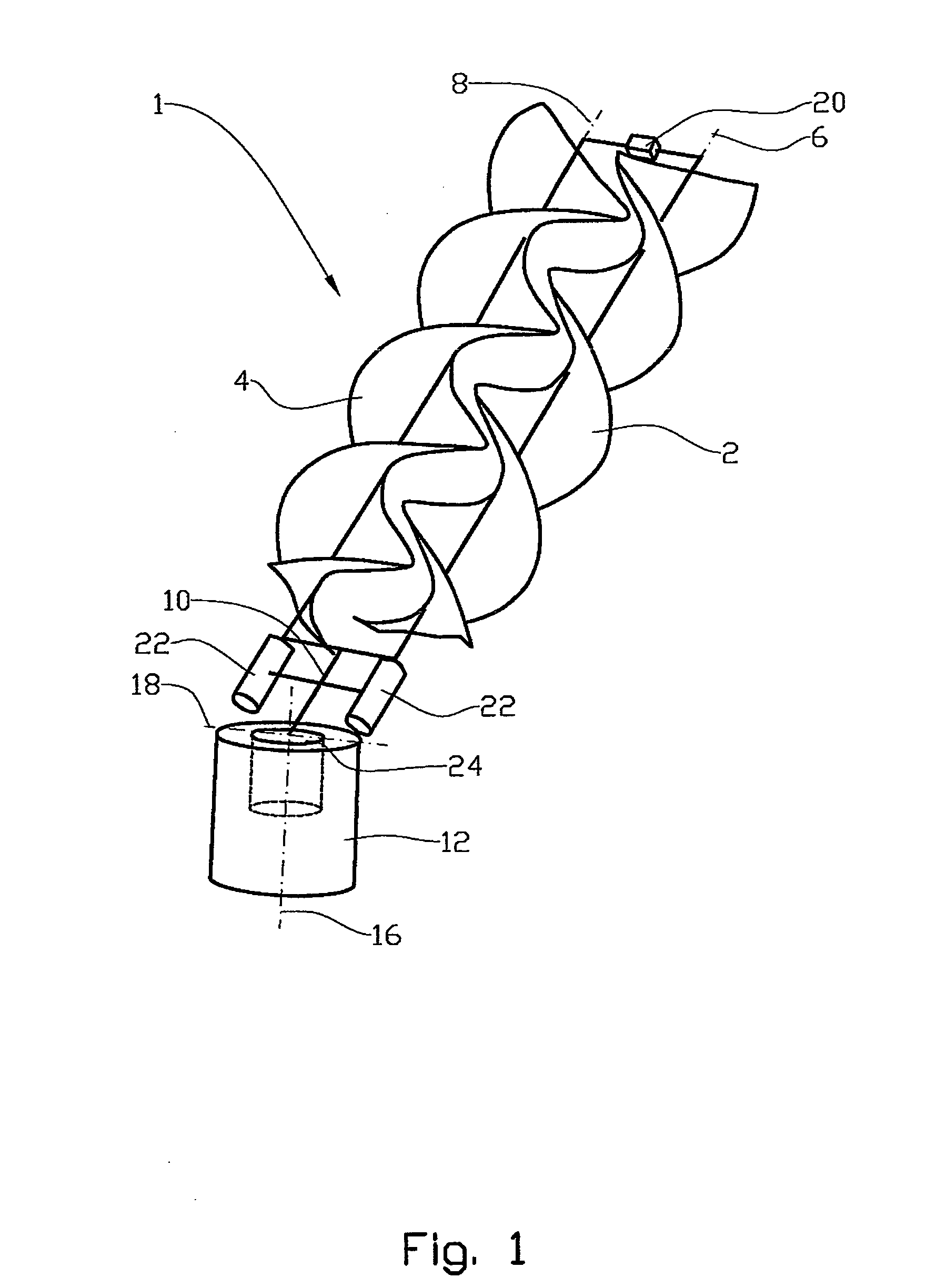
[0027]In the drawings, the reference numeral 1 indicates a turbine arrangement comprising a first screw turbine 2 and a second screw turbine 4. The screw turbines 2, 4 are rotatable around, respectively, a first turbine axis 6 and a second turbine axis 8.

[0028]The screw turbines 2, 4 are supported in a suspension means 10 which is connected to a bottom mount 12 which is placed in the seabed 14. The suspension means 10 is rotatable around a vertical axis 16 relative to the bottom mount 12 and around a rotatable horizontal axis 18.

[0029]The two screw turbines 2, 4, which are of opposite pitches and rotate in opposite directions of rotation, are connected to each other by means of a transmission 20.

[0030]Each of the screw turbines 2, 4 is connected to a respective power machine 22 which is formed, in this preferred exemplary embodiment, by an electric generator. Necessary wiring is not shown.

[0031]A rotary suspension means 24 is arranged in the bottom mount 12. The rotary suspension me...


PUM


Abstract

A turbine arrangement for extracting energy from flowing water, the turbine arrangement s including a screw turbine with a suspension means, buoyancy element and bottom mount, and necessary transmission elements for transmitting energy to a power machine, and the turbine arrangement including at least two parallel screw turbines.

Description

CROSS REFERENCE TO RELATED APPLICATIONS[0001]This application is the U.S. National Phase of PCT Application No. PCT / NO2009 / 000022 filed 19 Jan. 2009 which claims priority to Norwegian Patent Application No. 20080454 filed 24 Jan. 2008 both of which are incorporated herein by reference.STATEMENT REGARDING FEDERALLY SPONSORED RESEARCH[0002]Not ApplicableTHE NAMES OF THE PARTIES TO A JOINT RESEARCH AGREEMENT[0003]Not ApplicableIn REFERENCE TO A SEQUENCE LISTING[0004]Not ApplicableBACKGROUND OF THE INVENTION[0005]This invention relates to a turbine arrangement. More particularly, it relates to a turbine arrangement for extracting energy from flowing water, the turbine arrangement including a screw turbine with a suspension means, buoyancy element and bottom mount and also necessary transmission elements for transmitting energy to a power machine.[0006]It is well known that, for example, tidal flows contain considerable amounts of energy. However, it has turned out to be connected with c...

Claims


Application Information

Patent Timeline
IPC IPC(8): F03B17/06
CPCF03B17/061F05B2240/243Y02E10/38Y02E10/28F05B2240/30Y02E10/30Y02E10/20
Inventor EIELSEN, JAN INGE
Owner FLUMILL
Learn More