[0012]In the metering device of the present invention, by rotation around the symmetry axis of the cylinder-
plunger system of the syringe which is inserted into the metering device, i.e. around the axis of the metering device, a syringe when being inserted is aligned by the co-operation of the alignment
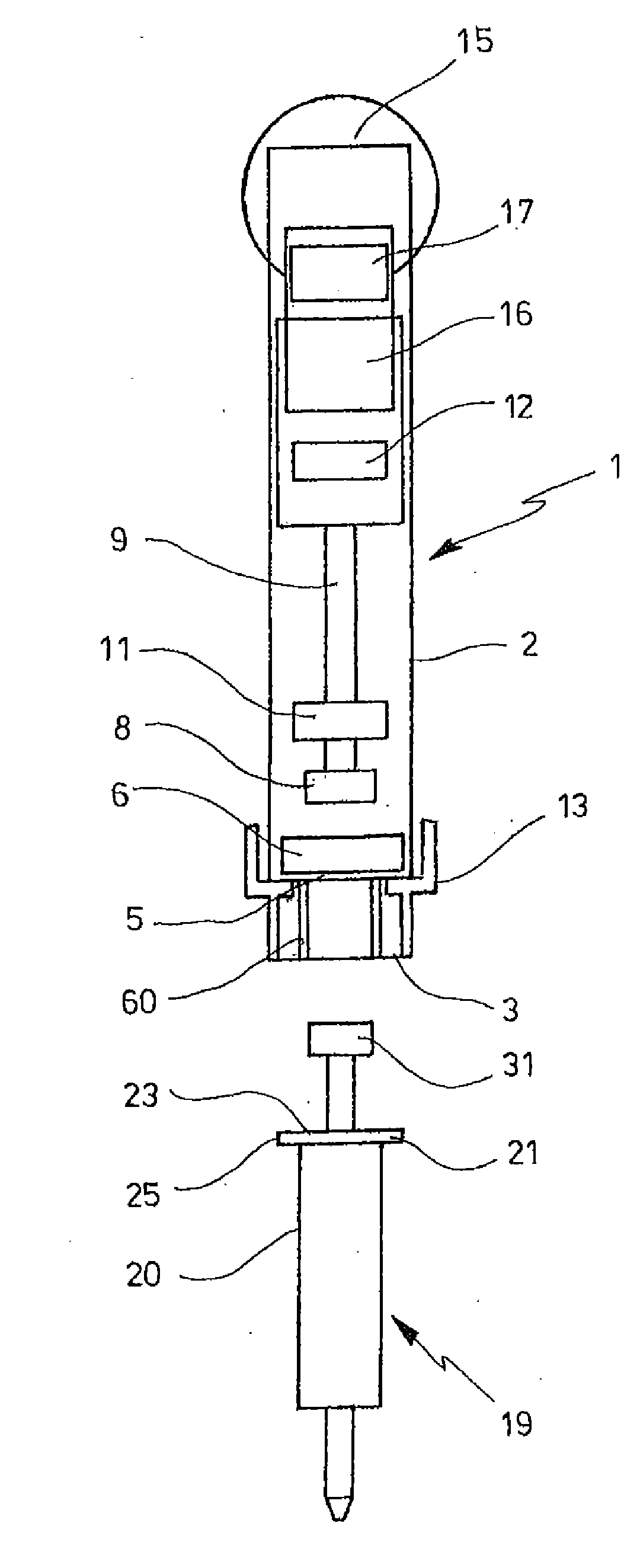
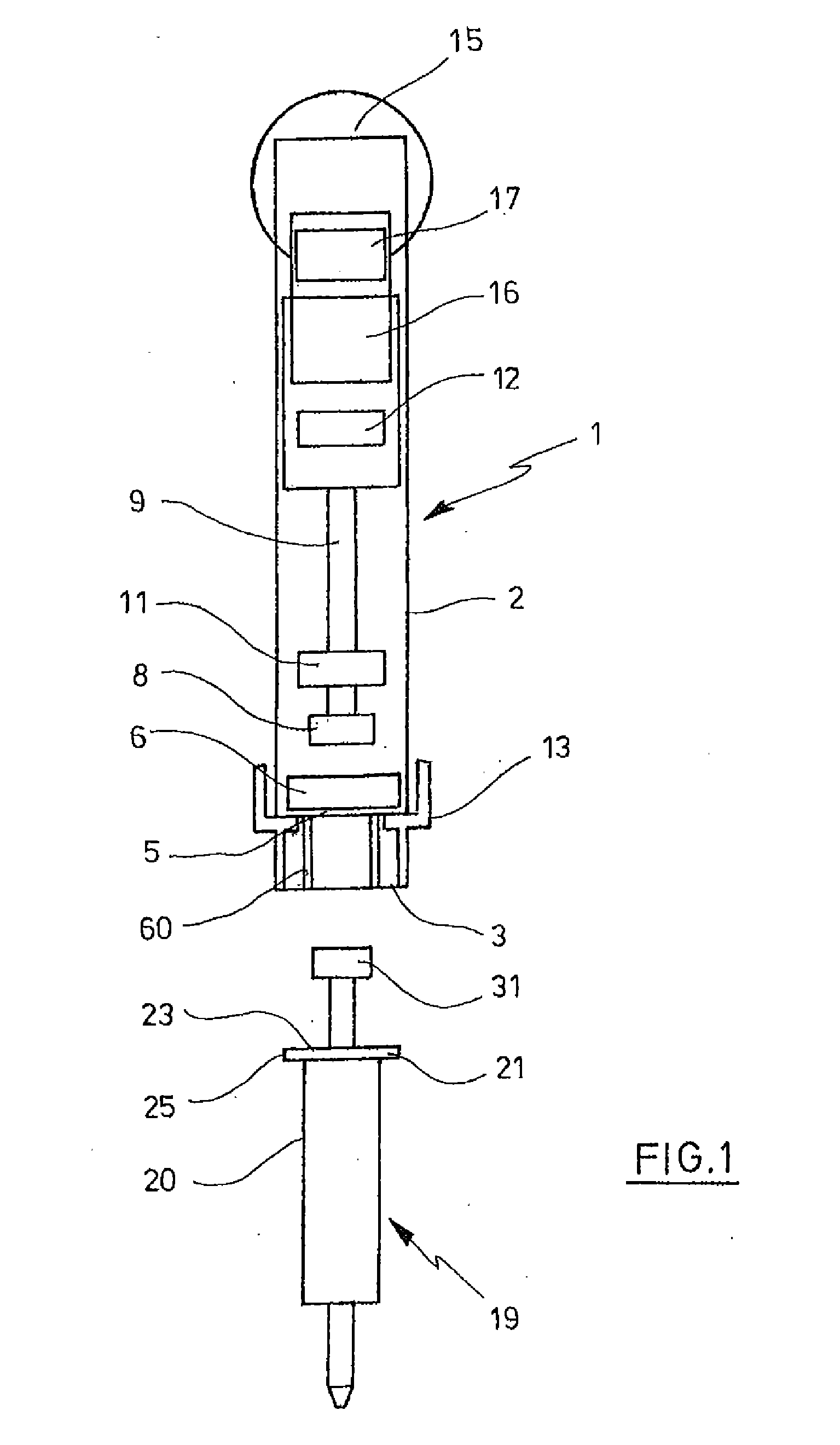
nose with the axial guiding means into an angular position in which each sensing surface of the syringe provided for this is axially directed towards a sensing means. In this, with its fastening portion formed on the cylinder and preferably being annular-shaped and located preferably at the upper end of the cylinder, and also with its plunger rod, the syringe arrives in the fastening position in which it is detachably held by way of the fastening device. The
pipette can sense the sensing surfaces with its sensing device and acquire the information about the syringe and / or its condition that is contained in the number and / or the arrangement and / or the axial position of the sensing surfaces. This information may be processed and / or displayed via mechanical and / or electric and / or optical analysing units and / or via display units. Applying a great force it is possible to turn a syringe made of
polypropylene or another soft
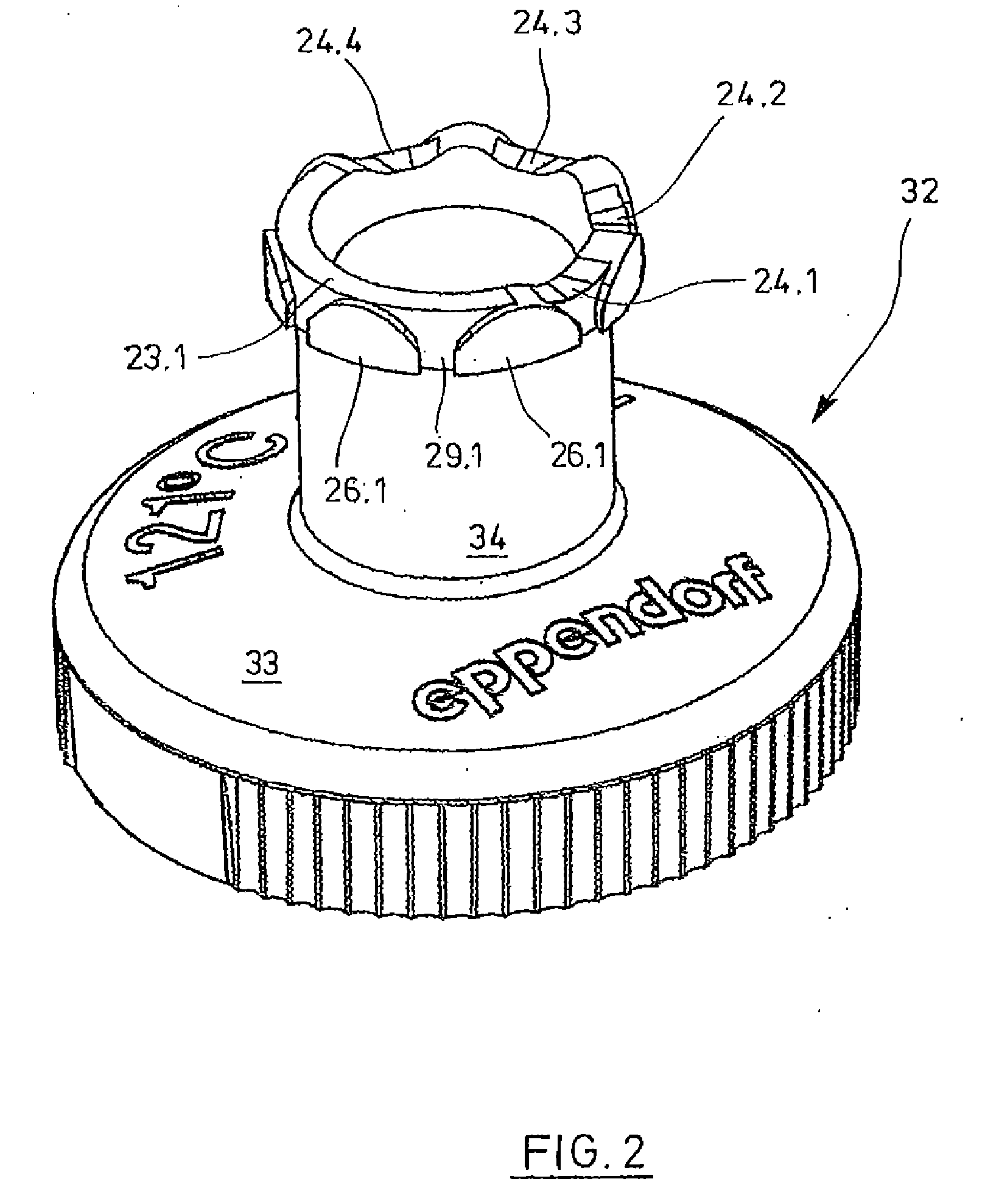
elastic plastic material away from this fastening position without releasing the fastening means before, wherein each alignment
nose is pressed along an associated guiding means under deformation. However, the present invention prevents that a damage of the preferably annular sensing device is accompanied by this. This is achieved by the preferably annular guiding means, which receives the at least one alignment nose in at least one indentation, provided that the syringe is correctly directed towards a sensing means with every sensing surface that is provided for this. When twisting the syringe, the at least one sensing surface slides from out the at least one indentation to the at least one raised surface which has a greater distance from the sensing device, so that the syringe cylinder is displaced away from the sensing device. In this, the sensing surfaces are displaced away from the annular sensing device, so that they do not damage the sensing means projecting from there and the sensing means are actuated no more. In the twisting, the fastening portion is preferably moved away from the annular sensing device so far that the sensing surfaces just no more touch the sensing means. Thus, the present invention takes the finding into account that a forced twisting of the syringe out of its fastening position in the metering device cannot be prevented due to the soft
elastic plastic materials that are used for the syringe. However, the metering device of the present invention prevents damage of the expensive sensing device by having means which transform a rotation of the syringe with respect to the
pipette into a shifting apart of fastening portion and sensing device.
[0018]In principle, the preferably annular sensing device may be disposed rigidly with respect to the accommodation. In a preferred embodiment, it is supported in the accommodation by way of at least one spring means acting axially against the displacement direction of the fastening portion. The spring means catches when the
pipette is inserted. Through this, tolerances are compensated and damage of the sensing device is avoided.
[0019]Springy holding means can exist for the fastening portion, so that fastening portion and sensing device can be displaced away from each other when the syringe is rotated. For instance, the fastening devices can be realised in a springy fashion. Further, it is possible to make the fastening portion springy on locations that are held by the fastening devices. According to a preferred embodiment, the preferably annular guiding means is connected to the sensing device and is supported in the accommodation by way of the at least one spring means. In this embodiment, twisting of the syringe that is detachably held in the pipette results in a movement of the annular guiding means, accompanied by taking along the preferably annular sensing device, wherein the at least one spring means catches in. As a result, the sensing device evades from the sensing surfaces of the syringe and will not be damaged.
[0020]The springy realisation of sensing devices, and as the case may be of guiding means, facilitates the automatic separation of pipette and syringe after releasing the fastening means.
[0023]Gradual removal of the fastening portion from the sensing device when the syringe is rotated in the pipette can be made sure by a suitable contour of the alignment nose in particular. For this purpose, the alignment nose may be rounded or chamfered on both side at the upside. According to a preferred embodiment, the guiding contour gradually ascends between the indentations and the raised parts. This favours a smooth gliding of the alignment noses over the guiding contour in the rotation of the syringe, in particular in co-operation with rounded or chamfered sides of the at least one alignment nose. According to a further embodiment, the transitions between the indentations and the raised parts are ramp-shaped and / or rounded.

