
Dose delivery device with gearing mechanism

a technology of gearing mechanism and dose setting member, which is applied in the direction of medical syringes, infusion syringes, ampoule syringes, etc., can solve the problems of high precision, complicated mechanism, and very limited friction force loss, so as to reduce complexity and production costs of devices, avoid the use of a more complicated connection to the dose setting member, and facilitate the integration of the spring mechanism

Active Publication Date: 2010-10-21
PHILLIPS MEDISIZE LLC
View PDF2 Cites 40 Cited by
  • Summary
  • Abstract
  • Description
  • Claims
  • Application Information

AI Technical Summary

Benefits of technology

[0011]By using threads of opposite direction, very high pitches can be used and, thus, very small force reductions due to friction can be obtained.
[0029]Alternatively, the dose setting click and indexing of the dose setting member can be radial between a click item locked to the driver and the dose setting member. This has the advantage, that the indexing torque can be set to be high and the spring force to engage the dose setting member and the scale drum can be set to be low, or to be zero if there is no engagement / disengagement.

Problems solved by technology

This embodiment provides a gearing in movement, but does not reduce the needed injection force very much, as the transmission from linear movement to rotational movement and back from rotational to linear movement eats up most of the obtained force reduction due to friction.
However, this development provides a complicated voluminous mechanical solution which demands high precision.
As none of the parts of the injection mechanism rotate in threads during injection, the loss of force due to friction is very limited.
However, this mechanism is rather complicated, and it is not suited for simple, disposable dose delivery devices.
Further more this concept does not allow the user to correct a wrongly set dose.

Method used


Image

  • Dose delivery device with gearing mechanism
  • Dose delivery device with gearing mechanism
  • Dose delivery device with gearing mechanism

Examples


Embodiment Construction

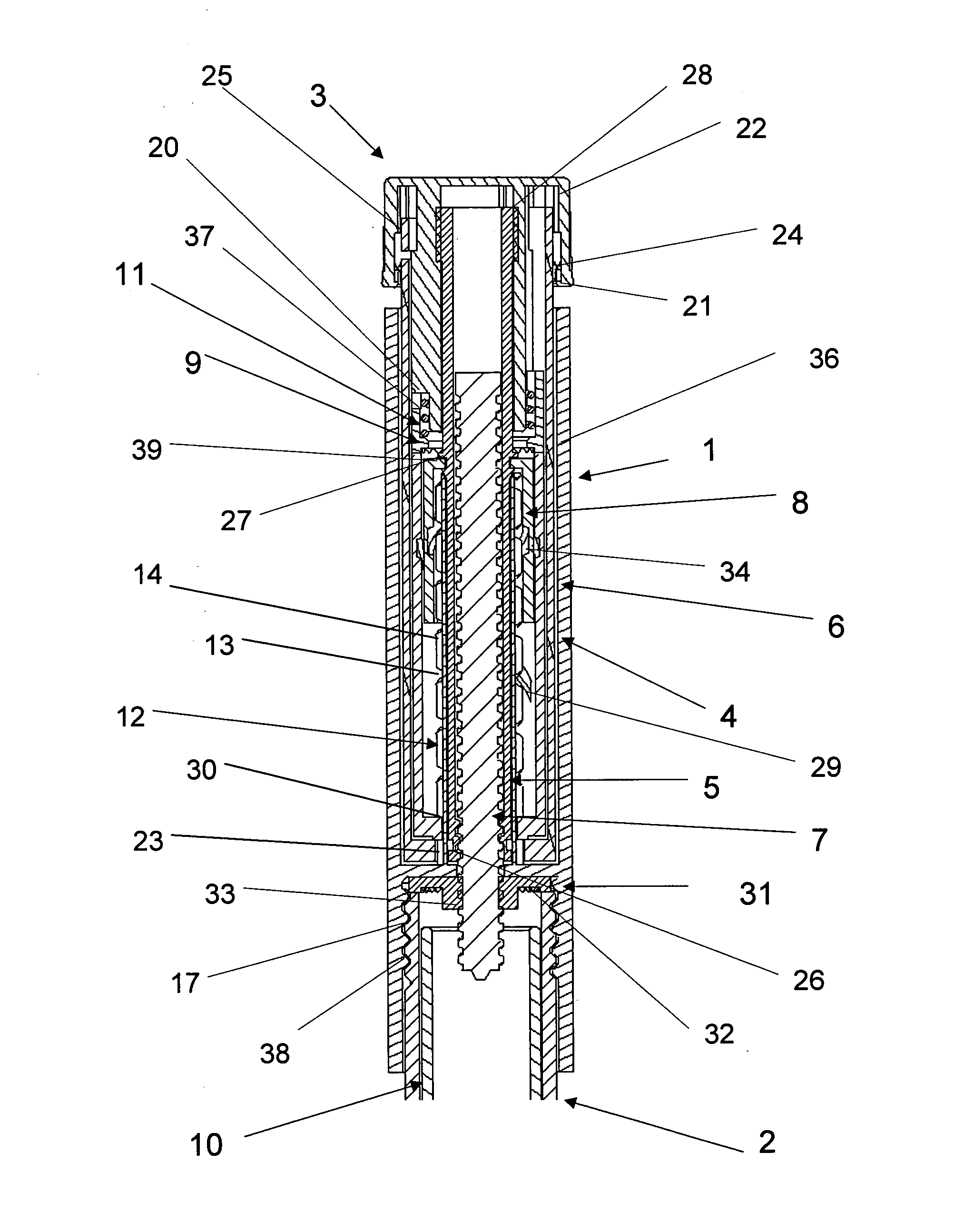
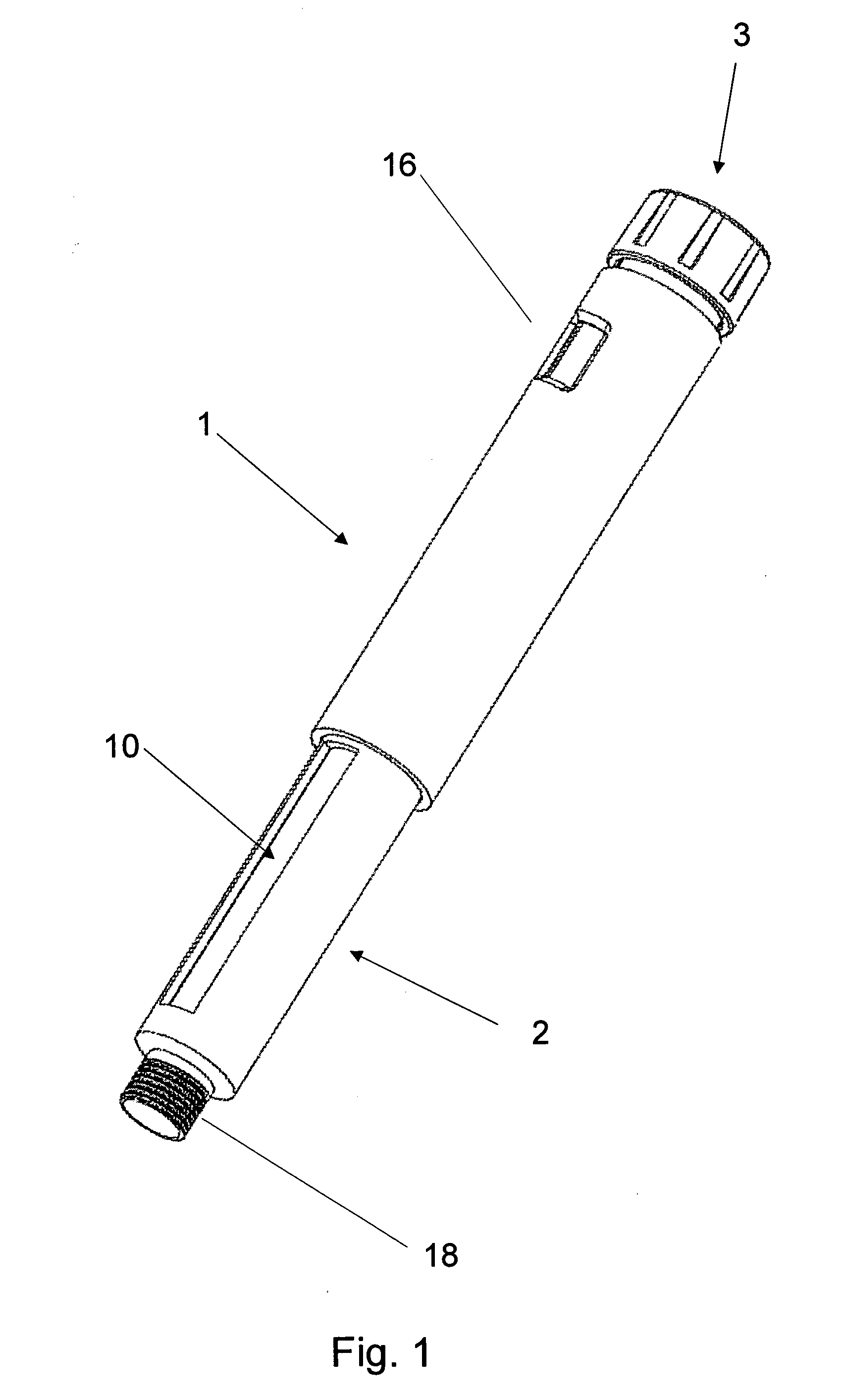
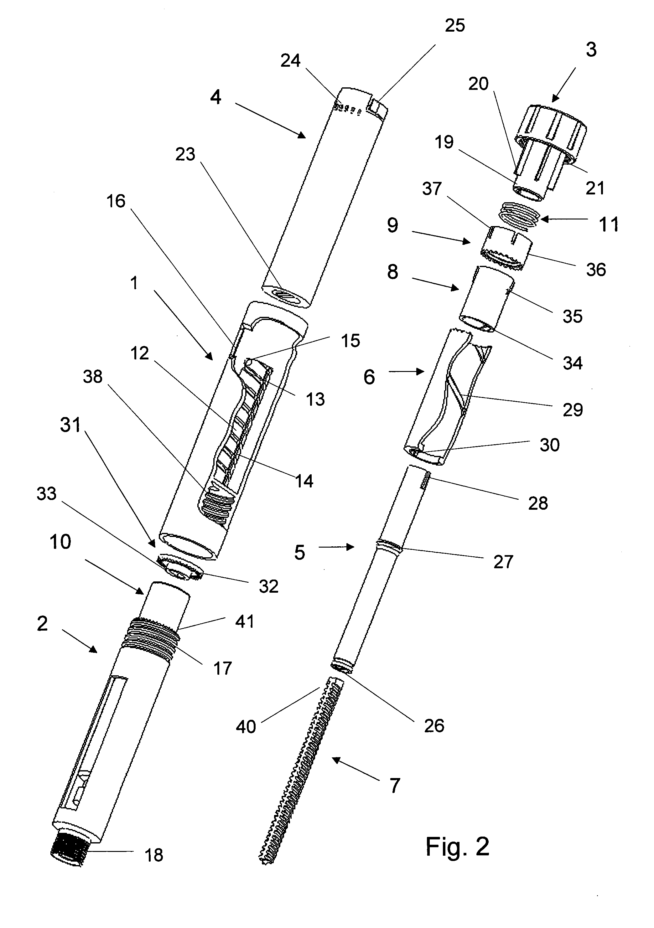
[0041]FIG. 1 shows a device according to the invention in an oblique view. Visible is the housing 1 comprising a window 16, where the amount of a set dose can be displayed, the dose setting member 3 by which a dose is set and injected and the cartridge holder 2 comprising a thread 18 for the attachment of a double-ended needle. The cartridge holder 2 also contains the medicine-filled cartridge 10. The cartridge 10 comprises a piston (not shown), which cooperates with the piston rod 7 of the injection system to expel a set dose of medicine from the cartridge 10 out through the needle. The cooperation between the different elements of the device will be described in the following.

[0042]The dose setting member 3 of the shown embodiment is to be comprehended as an element by which a dose can be both set and injected. In other embodiments of the invention, the functions of the dose setting member 3 are divided into two elements—a dose setting button and an injection button. In some embod...


PUM


Abstract

A dose delivery device is disclosed where a dose can be set by rotating a dose setting member, whereby a push button is elevated from one end of the device a distance proportional to the set dose from a position fixed relative to the housing, and where the set dose can then be injected by pressing the push button back to its non-elevated position, through which motion a piston rod will move the same or a different distance due to a gearing mechanism being provided between the push button and the piston rod, where the gearing mechanism includes at least a first and a second thread on one or more parts that are rotationally coupled to each other, the first thread engaging a driver, the second thread engaging an element rotationally locked to the driver, one of the threads of the gearing mechanism being left-handed and the other one being right-handed.

Description

TECHNICAL FIELD[0001]The invention relates to a dose delivery device, wherein a dose can be set by rotating a dose setting member, whereby a push button is elevated from one end of the device, and the set dose can then be injected by pressing the push button back to its non-elevated position, thereby moving a piston rod co-operating with the piston in a cartridge and expelling a medicament out of the cartridge through a needle.BACKGROUND[0002]From EP 0 327 910 is known an injection device in which a dose is set in the classic way by rotating a tubular injection button engaging a threaded piston rod, thereby causing the injection button to elevate from the end of the injection device. By pressing down the injection button until abutment with a fixed stop, the threaded piston rod is moved a distance corresponding to the movement of the injection button. The piston rod mates a piston in a cartridge and medicine is expelled from the cartridge. This kind of injection device transmits the...

Claims


Application Information

Patent Timeline
IPC IPC(8): A61M5/315A61M5/24
CPCA61M5/24A61M5/31535A61M5/31541A61M5/31551A61M5/31558A61M5/3157A61M5/31543A61M5/31585A61M5/31593A61M2005/2407A61M2005/2488A61M2005/3152A61M5/31575
Inventor MOLLER, CLAUS SCHMIDT
Owner PHILLIPS MEDISIZE LLC
Learn More