Test unit for wound drainage dressings

a technology for testing units and wounds, applied in the direction of instruments, other medical devices, structural/machine measurement, etc., can solve the problem of difficulty in determining which wound drainage dressing is best used, and achieve the effect of uniform testing and optimized use of wound drainage dressings

Active Publication Date: 2010-10-21
MEDELA HLDG AG
View PDF5 Cites 9 Cited by
  • Summary
  • Abstract
  • Description
  • Claims
  • Application Information

AI Technical Summary

Benefits of technology

[0006]It is therefore an object of the invention to make available a device which permits uniform testing and optimized use of wound drainage dressings under conditions as close as possible to those encountered in practice.
[0014]Wound liquids of different compositions can be introduced into the simulated wound via the at least one supply line. It is possible to choose whether the wound liquid is supplied continuously, at predetermined time intervals or just once. The support surface permits easy and quick application of wound drainage dressings that are to be tested. These wound drainage dressings can be covered by an air-permeable, self-adhesive film, which is affixed to the support surface. However, they can also be used in the test unit along with the specific covers recommended by the manufacturer, for example rigid caps. In this case, the cap is simply affixed to the support surface, for example by means of an airtight, self-adhesive film.
[0015]The main body of the test unit preferably has a plane-parallel base plate, a supply plate and, arranged between these, a sealing plate, said supply plate having the channels and at least one recess for forming the cavity. The main body therefore has a relatively simple structure and can be produced inexpensively. It is also easy to clean, since the channels and the recess are easily accessible when the main body has been unscrewed.
[0016]Another advantage of the main body in this configuration is that several supply plates can be used with the same base plate and intermediate plate. In this way, the test unit is able to simulate a wide variety of sizes and arrangements of cavities and channels.

Problems solved by technology

However, it is difficult to establish which wound drainage dressing is best used on which wound and with which suction pressure.

Method used


Image

  • Test unit for wound drainage dressings
  • Test unit for wound drainage dressings
  • Test unit for wound drainage dressings

Examples


Embodiment Construction

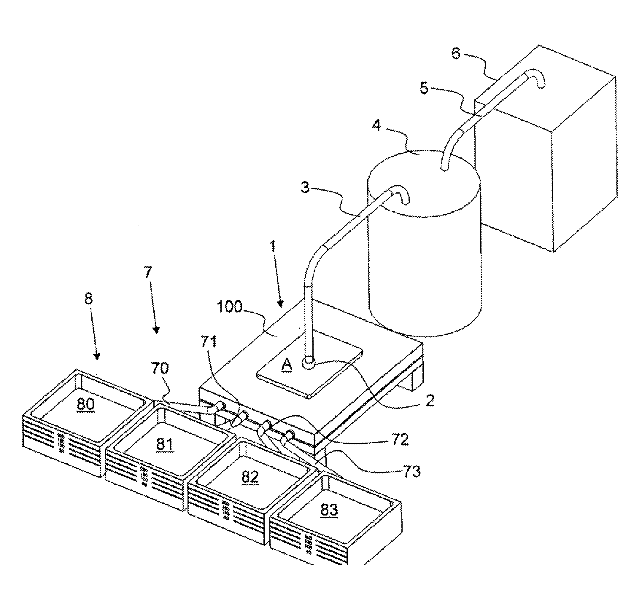
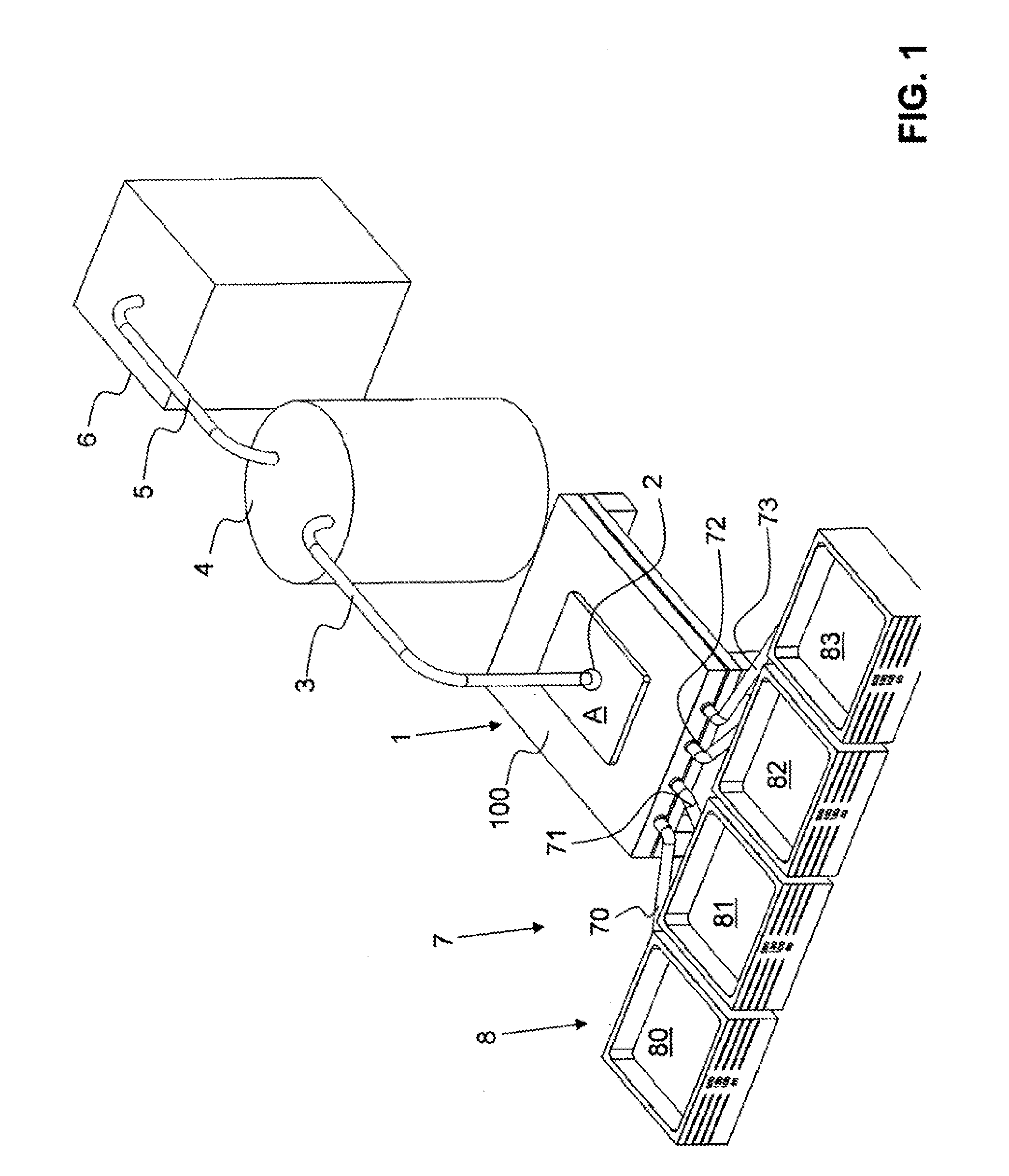
[0061]FIG. 1 shows a schematic representation of a test system according to the invention. It has a main body 1 of a test unit, a vacuum attachment 2, which is arranged on the main body 1 or can be connected thereto in an airtight manner via a wound cover A, a drainage line 3 connected to the vacuum attachment 2, a drainage container 4, into which the drainage line 3 opens, a pump line 5 leading from the drainage container 4, and a suction pump 6 connected to the pump line 5.

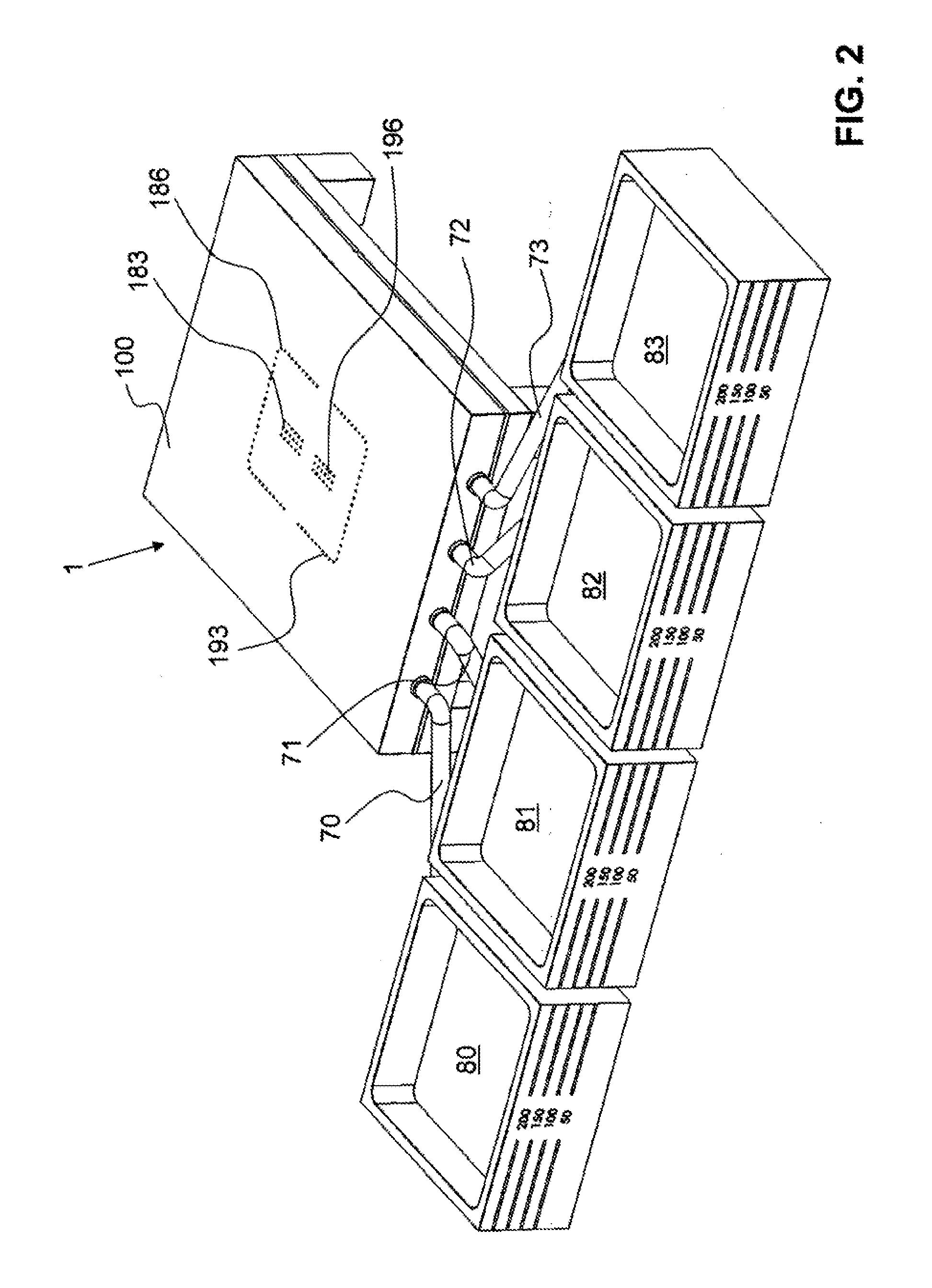
[0062]The main body 1 is also connected to a liquid reservoir system 8 via a connecting line system 7, which has at least one connecting line 70, 71, 72, 73. This liquid reservoir system 8 has at least one liquid reservoir 80, 81, 82, 83. The reservoirs 80, 81, 82, 83 preferably have a level indicator, as can be seen in FIG. 2.

[0063]The main body 1 has (see FIGS. 1 and 2) a support surface 100, which is preferably flat and has several channels 183, 186, 193, 196 leading into the interior of the main body 1. A wo...


PUM


Abstract

The invention relates to a test unit for wound drainage coverings comprising: a base body with at least one cavity; at least one supply line that runs through the base body and which connects an outer side of the base body to the cavity; a surface of the base body that is embodied as a support surface for supporting wound coverings and the wound drainage coverings thereof and several channels that run through the base body, the channels connecting the cavities to the support surface. Low pressure can be produced in the cavity and the channels when the support surface is covered in an air-tight manner. As a result, wound drainage applications are tested in different ways using simple and economical means.

Description

CROSS REFERENCE TO RELATED APPLICATIONS[0001]This application claims priority to International Application Serial No. PCT / CH2008 / 000465 filed Nov. 4, 2008, which claims priority to Swiss Patent Application No. 01734 / 07 filed Nov. 8, 2007, the contents of which are incorporated by reference herein in their entirety.TECHNICAL FIELD[0002]The invention relates to a test unit for wound drainage dressings.PRIOR ART[0003]It is known to treat large or poorly healing wounds using a vacuum drainage device. WO 94 / 20041, for example, describes this. A cover, for example a film or a stiff cap, is placed over the wound, such that a wound space is obtained. A drainage tube is inserted into the wound space from the outside and is connected to a suction pump in order to suck wound secretions out of the wound. In order to fill the wound space and, in particular, to distribute the vacuum uniformly across the surface of the wound, a wound dressing is placed on the wound. This wound dressing is usually ...

Claims


Application Information

Patent Timeline
Patent Type & Authority Applications(United States)
IPC IPC(8): A61M27/00G01M19/00G01M99/00
CPCA61M1/00A61M2209/02A61M1/0088A61M1/982A61M1/915A61M1/92
Inventor LARSSON, MICHAELFURRER, SIMON
Owner MEDELA HLDG AG
Why Eureka
Try Eureka