Clamps used for interconnecting a bone anchor to a rod

Active Publication Date: 2010-10-21
DEPUY SYNTHES PROD INC
View PDF83 Cites 116 Cited by
  • Summary
  • Abstract
  • Description
  • Claims
  • Application Information

AI Technical Summary

Benefits of technology

[0007]The present invention relates to a clamp, and, more particularly, to a clamp for securing the position of a bone anchor with respect to a longitudinal rod in a posterior spinal fixation procedure. The clamp may include a housing, a rod clamping assembly, and a bone anchor clamping assembly. The clamp preferably enables the longitudinal axis of the rod to be offset or laterally displaced from the longitudinal axis of the bone anchor. The rod clamping assembly may be moveably associated, preferably slidably coupled, to the housing so that

Problems solved by technology

In use, rotation of the rotatable member to a locked position may cause a downward force onto the slider member, which in turn may cause the slider member to contact the housing and may cause the collet to move with respect to the housing, which in turn may cause the position of the slider member and the position of the bone anchor to be fixed with respect to the housing.
In addition, rotation

Method used


Image

  • Clamps used for interconnecting a bone anchor to a rod
  • Clamps used for interconnecting a bone anchor to a rod
  • Clamps used for interconnecting a bone anchor to a rod

Examples


Embodiment Construction

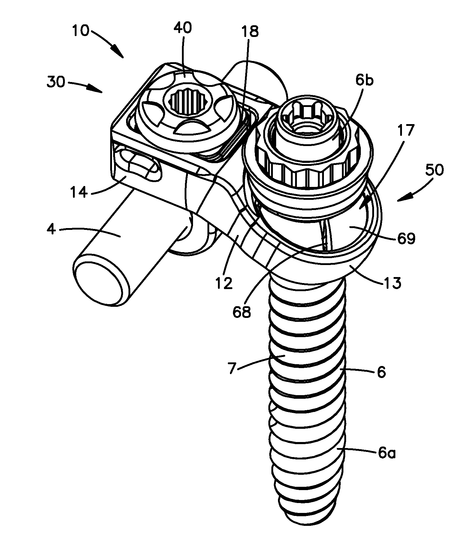
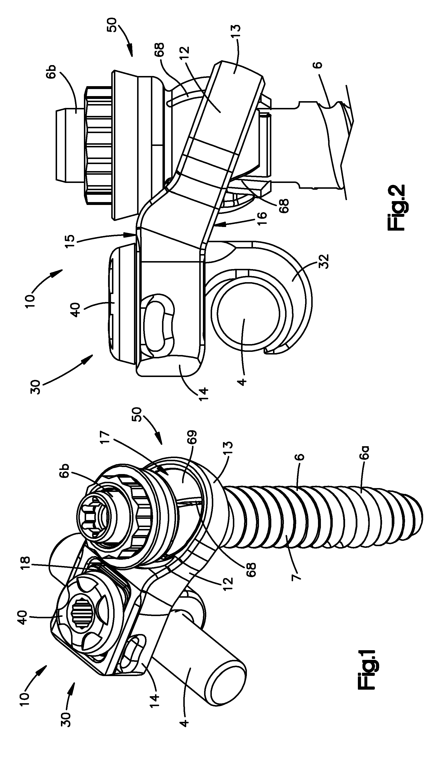
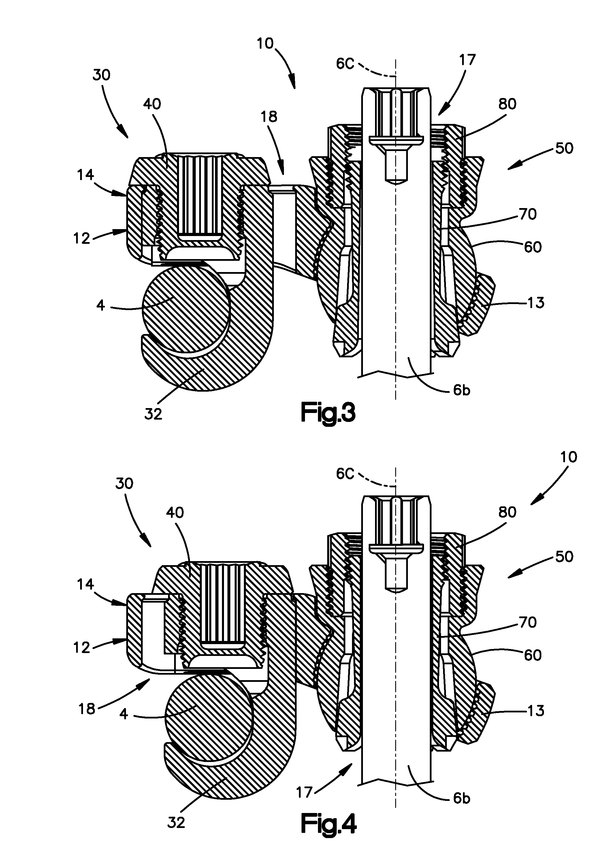
[0084]Certain exemplary embodiments will now be described with reference to the drawings. In general, such embodiments relate to a clamp, by way of non-limiting example, a clamp for use in securing a bone anchor, and hence a bone (preferably a vertebra), with respect to a longitudinal rod (preferably a spinal rod). The clamp may include a housing, a rod clamping assembly, and a bone anchor clamping assembly. The clamp preferably enables the longitudinal axis of the rod to be offset or laterally displaced from the longitudinal axis of the bone anchor such that the longitudinal rod may be secured at a position laterally offset or displaced from the bone anchor. The rod clamping assembly may include a first position (e.g., a slack configuration) and a second position (e.g., a fastened configuration) wherein, when in the first position, the rod is moveable with respect to the clamp and, when in the second position, the position of the rod is fixed with respect to the clamp. That is, the...


PUM


Abstract

The present invention relates to a clamp, and, more particularly, to a clamp for securing the position of a bone anchor with respect to a longitudinal rod, preferably for use in the spine. The clamp may include a housing, a rod clamping assembly, and a bone anchor clamping assembly. The clamp preferably enables the longitudinal axis of the rod to be offset or laterally displaced from the longitudinal axis of the bone anchor. The rod clamping assembly and the bone anchor clamping assembly are preferably moveably coupled to the housing in order to provide increased flexibility to better accommodate the location and geometry of the longitudinal rod and to better accommodate bone positioning.

Description

CROSS REFERENCE TO RELATED APPLICATIONS[0001]This application claims priority to U.S. provisional patent application Ser. No. 60 / 950,809, filed Jul. 19, 2007 and is a continuation-in-part of International patent application serial No. PCT / US2007 / 074633, filed Jul. 27, 2007. The content of these applications is hereby incorporated by reference in their entirety.FIELD OF THE INVENTION[0002]The present invention relates to a clamp, and, more particularly, to a clamp for securing the position of a bone anchor with respect to a longitudinal rod, preferably for use in the spine.BACKGROUND OF THE INVENTION[0003]Spinal fusion is a procedure that involves joining two or more adjacent vertebrae with a bone fixation device to restrict movement of the vertebra with respect to one another. Spinal fixation devices are used in spine surgery to align, stabilize and / or fix a desired relationship between adjacent vertebral bodies. Such devices typically include a spinal fixation element, such as, for...

Claims


Application Information

Patent Timeline
IPC IPC(8): A61B17/70
CPCA61B17/7035A61B17/7037A61B17/8897A61B17/7076A61B17/7083A61B17/7041A61B17/70A61B17/82
Inventor GABELBERGER, JOSEFMCSHANE, EDWARDVENNARD, DANIELANGERT, NICHOLASDAVIS, BARCLAYSCHWER, STEFANSCHAER, MANUELNORMAN, LEE-ANNHELBEISEN, RETONIEDERMANN, BENNO
Owner DEPUY SYNTHES PROD INC
Why Eureka
Try Eureka