Rendering and modifying cad design entities in object-oriented applications

a design entity and object-oriented technology, applied in special data processing applications, instruments, electric digital data processing, etc., can solve the problems of limiting the user's ability to layout or specify furniture, affecting the effect of design, and requiring laborious changes, so as to achieve the effect of viewing a cad-based design

Active Publication Date: 2010-10-21
ARMSTRONG WORLD INDUSTRIES +1
View PDF100 Cites 63 Cited by
  • Summary
  • Abstract
  • Description
  • Claims
  • Application Information

AI Technical Summary

Benefits of technology

[0015]Implementations of the present invention overcome one or more problems in the art with systems, methods, and computer program products configured to instantly render user-drawn CAD design elements such as blocks and / or lines (in a CAD application program) as one or more design elements in a separate, three-dimensional interface. This rendering is a three dimensional rendering, enabling the user to move, rotate, “fly-through” or edit the one or more design elements in the three-dimensional interface. This can allow the user to effectively view a CAD-based design in full context, even if there may be certain errors or inconsistencies in the design. In addition, in at least one implementation, the user can also convert the design elements to intelligent objects, and allow the system to warn or automatically correct for any errors or deficiencies in the design. This can allow the user to correlate the user's design changes in the CAD interface with real-world considerations, ensuring accuracy of the user's viewing experience, as well as of ordering and manufacturing requests.

Problems solved by technology

In addition, CAD programs generally limit the user's ability to layout or specify furniture with only rudimentary geometry-based applications.
Unfortunately, however, there is typically no true product intelligence within conventional geometry-based design software.
If the user desires to change the elements associated with a block, such change may be laborious, and often requires the user starting the design over from the start.
Furthermore, the representative views that the geometry-based design program provides to the user of the products are typically rudimentary and subject to interpretation.
While some application programs may provide three-dimensional views, if they exist at all, such programs typically do not provide such views with the appropriate colors, finishes, materials, shadowing, shading, transparency or reflectivity.
Thus, the user may still need to manually replicate any change or request in one view to another view in another application, which results in repeat rendering of those additional views.
Furthermore, more complicated renderings that could allow a “fly through” navigation-type experience can take conventional rendering applications minutes, hours, or even days to render.
Unfortunately, traditional conventional object-oriented design programs still have other limitations when importing data from linear records since the user will still need to supply finishes, materials, shadowing, shading, and reflectivity with respect to the imported CAD blocks.
One such limitation can be due to the otherwise advantages of the object-oriented application itself.
For example, if a CAD-based design comprised design choices that were not currently available in inventory (e.g., drawing a blue colored glass table when only black or brown wood grain tables are available), the object-oriented software might not render the user's design as drawn in the CAD program without warning.

Method used


Image

  • Rendering and modifying cad design entities in object-oriented applications
  • Rendering and modifying cad design entities in object-oriented applications
  • Rendering and modifying cad design entities in object-oriented applications

Examples


Embodiment Construction

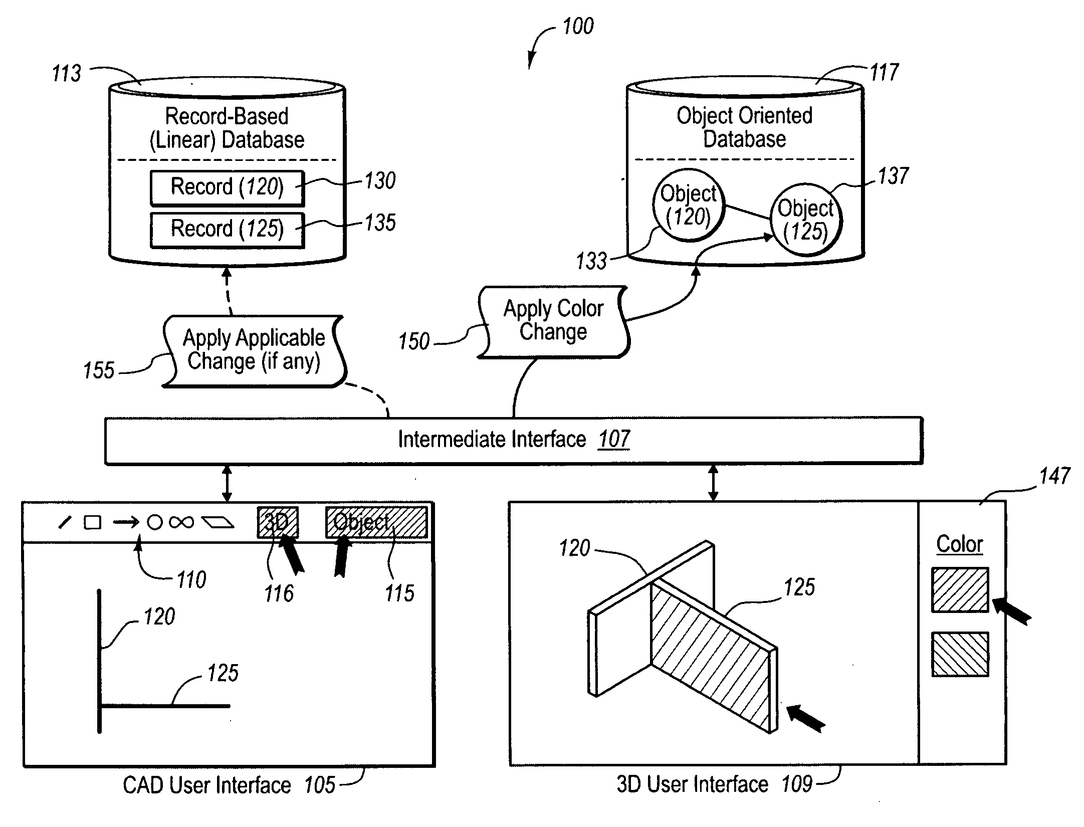
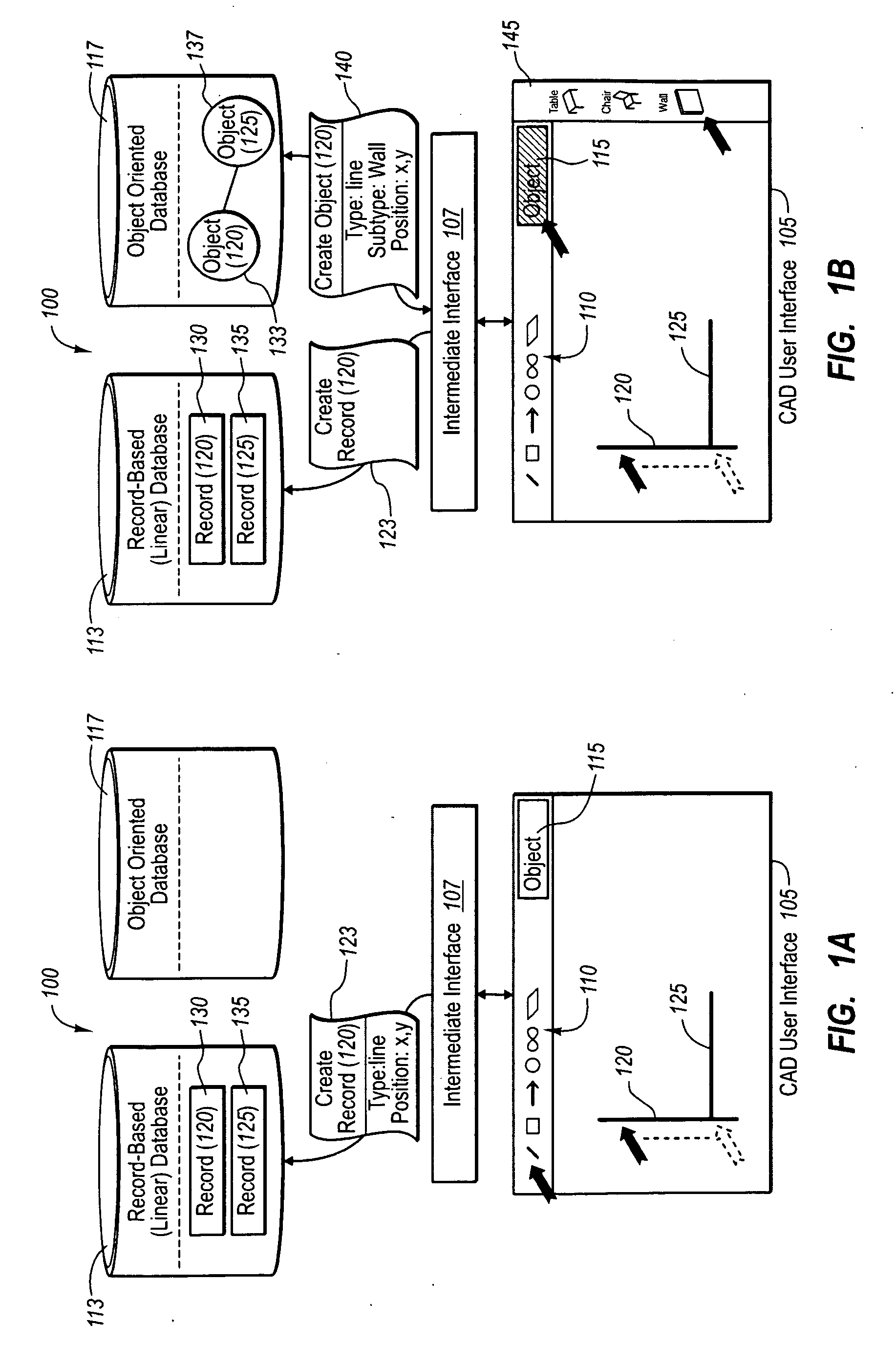
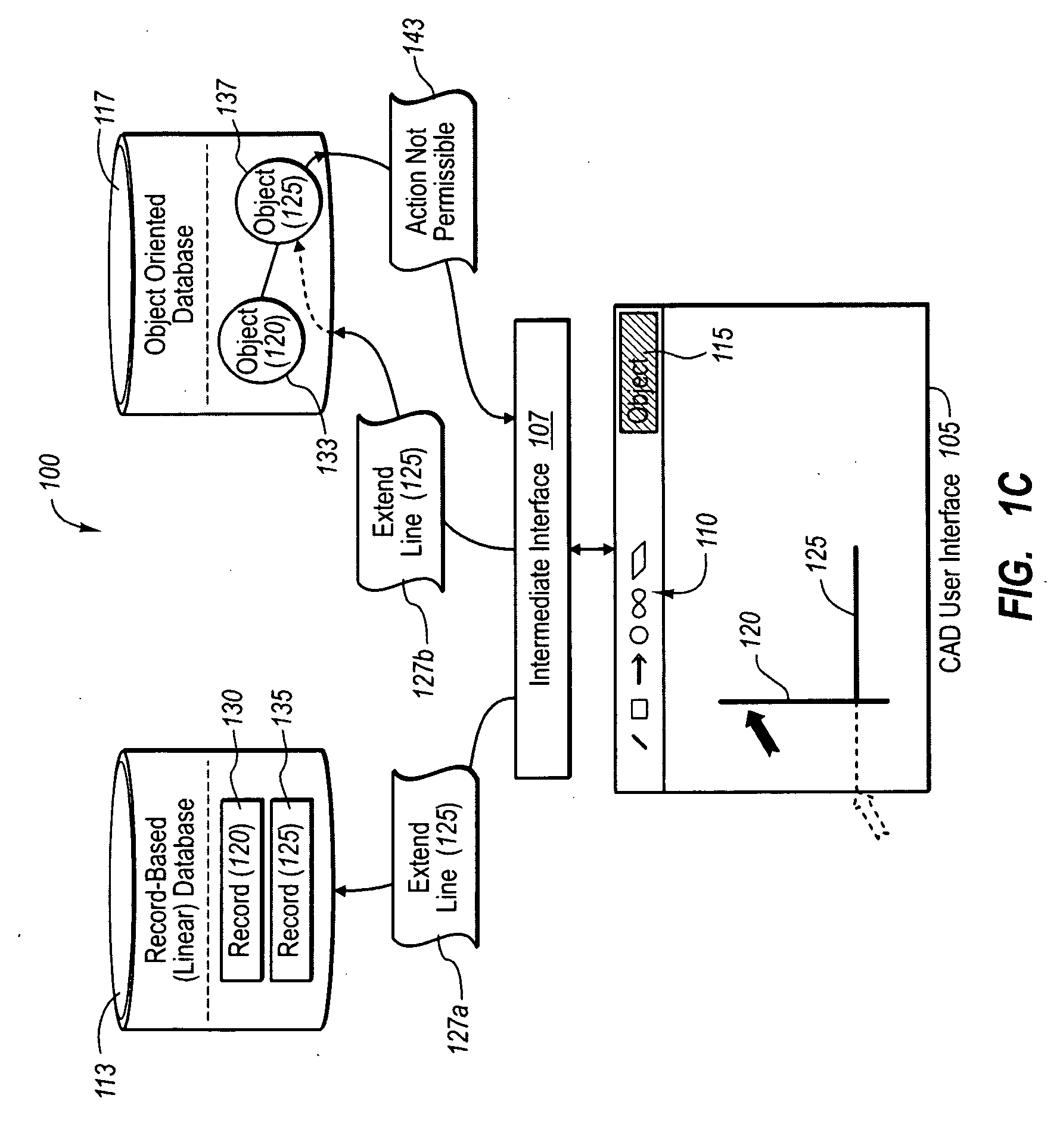
[0032]The present invention extends to systems, methods, and computer program products configured to instantly render user-drawn CAD design elements such as blocks and / or lines (in a CAD application program) as one or more design elements in a separate, three-dimensional interface. This rendering is a three dimensional rendering, enabling the user to move, rotate, “fly-through” or edit the one or more design elements in the three-dimensional interface. This can allow the user to effectively view a CAD-based design in full context, even if there may be certain errors or inconsistencies in the design. In addition, in at least one implementation, the user can also convert the design elements to intelligent objects, and allow the system to warn or automatically correct for any errors or deficiencies in the design. This can allow the user to correlate the user's design changes in the CAD interface with real-world considerations, ensuring accuracy of the user's viewing experience, as well...


PUM


Abstract

An object-oriented design program provides is configured to instantly render in a three-dimensional interface user CAD designs received as CAD-based design elements (e.g., CAD blocks or lines). The object-oriented program renders the user CAD designs regardless of whether the user designs are practical, or use finishes or colors that are in-stock for the selected design elements. In addition, the object-oriented program can also create intelligent software objects for the CAD-based elements at a later time, upon request by the user. The intelligent software objects can be configured to automatically resolve themselves in view of one or more system limitations and rules in related components, and to replicate any such resolution back to the CAD-based blocks if desired. Thus, a user can have the benefits of instant 3D rendering of CAD drawings with or without the automatic resolution provided by intelligent software objects, depending on the situation.

Description

CROSS-REFERENCE TO RELATED APPLICATIONS[0001]This application is a U.S. National Stage Application corresponding to PCT / CA2009 / 000183, filed on Feb. 13, 2009, entitled “Rendering and Modifying CAD Design Entities in Object-Oriented Applications,” which claims the benefit of priority to U.S. Provisional Application No. 61 / 028,399, filed on Feb. 13, 2008, entitled “Automated Conversion of CAD-Based Blocks to Intelligent Rendered Objects in Object-Oriented Design Software.”[0002]This application is also a continuation-in-part of U.S. patent application Ser. No. 11 / 577,302, filed on Aug. 16, 2008, entitled “Integration of Object-Oriented Design Software with Record-Based CAD Software,” which is a 371 US National Stage Application corresponding to PCT Application No. CA07 / 000,241, filed on Feb. 16, 2007, which claims priority to U.S. Provisional Patent Application No. 60 / 774,096, filed on Feb. 16, 2006. The entire content of each of the aforementioned applications is incorporated herein ...

Claims


Application Information

Patent Timeline
Patent Type & Authority Applications(United States)
IPC IPC(8): G06F17/50G06F3/14G06F9/44
CPCG06F17/5004G06F30/13
Inventor LOBERG, BARRIE A.
Owner ARMSTRONG WORLD INDUSTRIES
Why Eureka
Try Eureka