Thermal cycler with optical detector

a technology of optical detector and cycler, which is applied in the direction of biomass after-treatment, process and machine control, fluorescence/phosphorescence, etc., can solve the problems of large thermal mass, long processing time, and inability to achieve temperature uniformity, and achieve efficient optical viewing of samples. , the effect of optimal thermal transfer

Inactive Publication Date: 2008-10-16
CEPHEID INC
View PDF46 Cites 56 Cited by
  • Summary
  • Abstract
  • Description
  • Claims
  • Application Information

AI Technical Summary

Benefits of technology

[0020]A reaction vessel and thermal cycler for performing heat-exchanged chemical reactions are provided. The reaction vessel a

Problems solved by technology

Such control of temperature may inhibit side reactions, the formation of unwanted bubbles, the degradation of components at certain temperatures, etc., which may occur at non-optimal temperatures.
Because of the large thermal mass of the aluminum block, heating and cooling rates are limited to about 1° C./sec resulting in longer processing times. For example, in the PCR application, fifty cycles may require two or more hours to complete.
One problem with these instruments is that the large thermal masses, required for temperature uniformity, take a long time (and or a large heating/cooling power source) to heat and to cool.
With these relatively slow heating and cooling rates, it has been observed that some processes requiring high control of temperature are inefficient.
F

Method used


Image

  • Thermal cycler with optical detector
  • Thermal cycler with optical detector
  • Thermal cycler with optical detector

Examples


Embodiment Construction

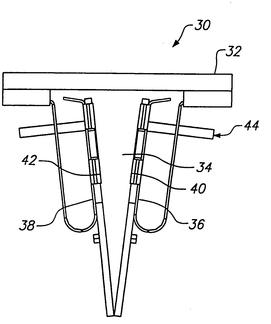
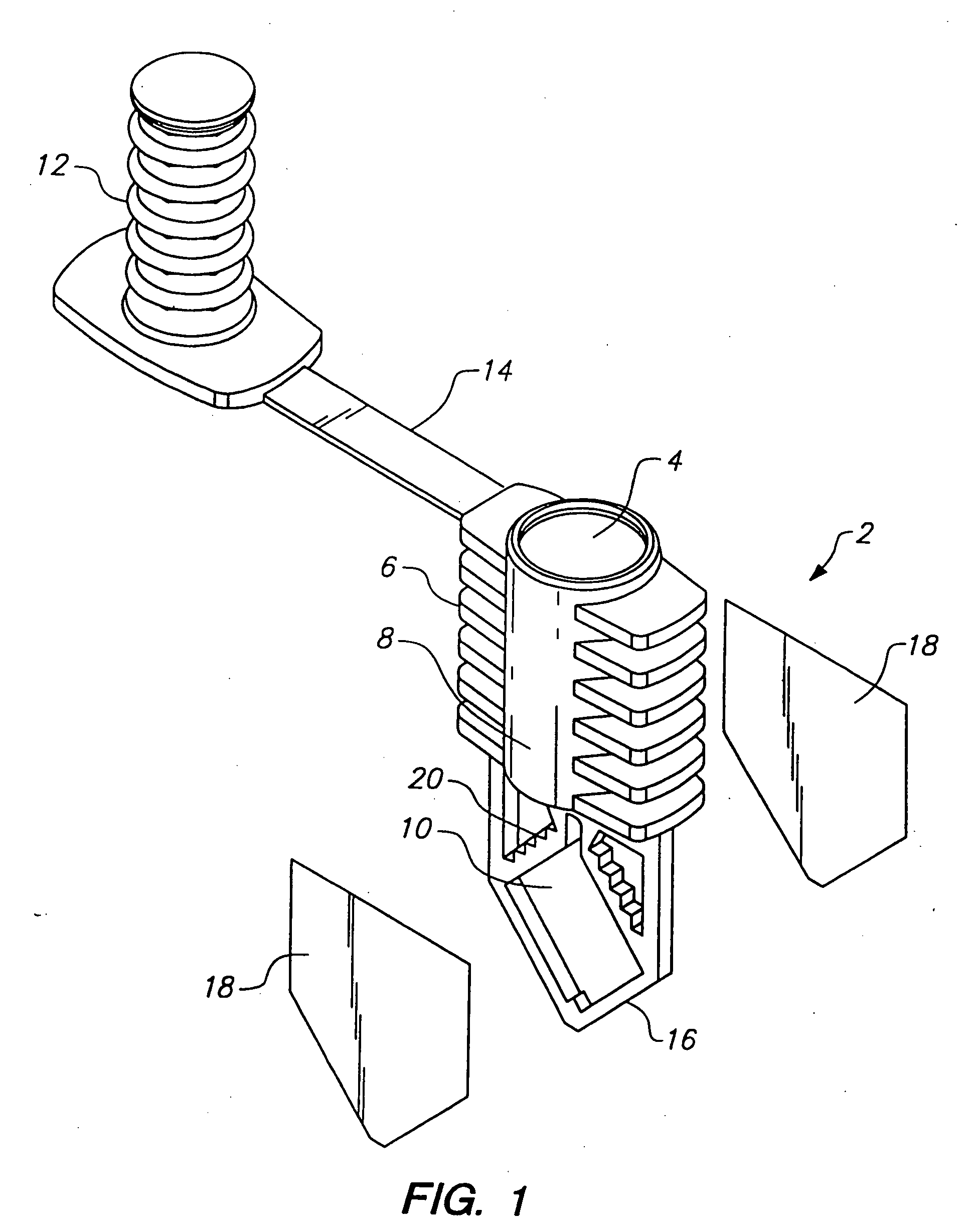
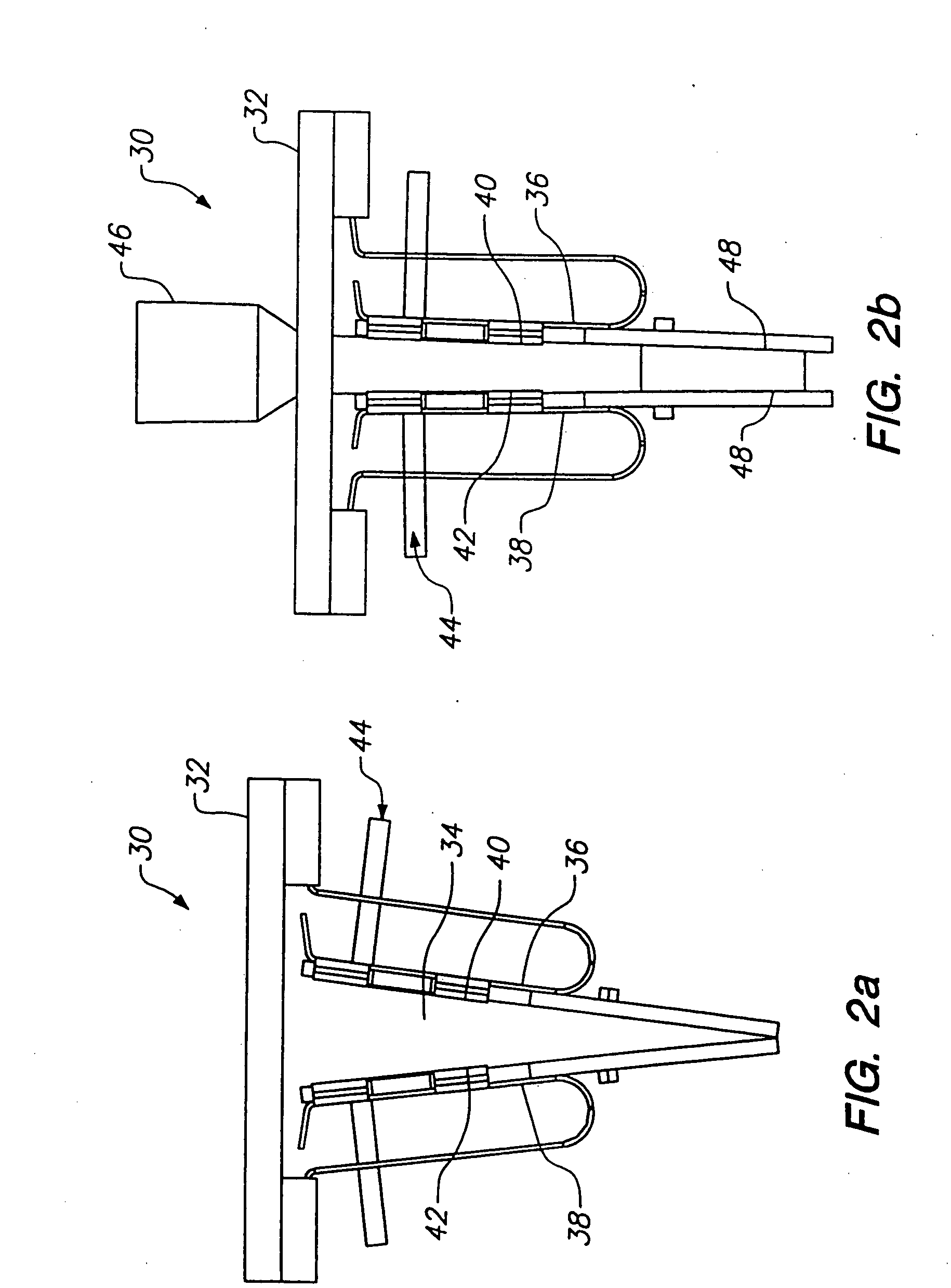
[0034]In general, this invention provides a low thermal mass heating and cooling assembly for the rapid heating and cooling of chemical solutions to perform reactions and for the efficient detection of the reaction products. The low thermal mass of the system ensures rapid heating and cooling rates since there is little material to heat and cool and because there is a high surface to volume ratio for thermal transfer. Those skilled in the art have only recently appreciated that rapid heating and cooling improves efficiency and decreases the amount of extraneous undesirable reactions, and that certain reactions could be performed with high thermal exchange rates.

[0035]The objectives of the invention are to greatly increase thermal exchange rates in chemical processes, such as PCR (up to 10× faster heating and cooling rates), to optimize temperature uniformity of the reactants, to accommodate high thermal expansion coefficients to minimize thermal-induced mechanical stress; maximize o...


PUM

PropertyMeasurementUnit
Angleaaaaaaaaaa
Angleaaaaaaaaaa
Wavelengthaaaaaaaaaa

Abstract

A reaction vessel having a reaction chamber for holding a sample is fabricated by producing a housing having a rigid frame defining the minor walls of the chamber. The housing also defines a port for introducing fluid into the chamber. At least one sheet or film is attached to the rigid frame to form at least one major wall of the chamber. In preferred embodiments, two sheets or films are attached to opposite sides of the rigid frame to form two opposing major walls of the chamber, the major walls being connected to each other by the minor walls.

Description

CONTINUING APPLICATION DATA[0001]This application is a continuation of U.S. patent application Ser. No. 10 / 379,004, filed Mar. 3, 2003, which is a division of U.S. patent application Ser. No. 09 / 194,374, filed Jul. 25, 2000, now issued as U.S. Pat. No. 6,565,815, which is the National Stage of International Application No. PCT / US98 / 03962, filed Mar. 2, 1998 which International Application is a continuation of U.S. patent application Ser. No. 08 / 808,325 filed Feb. 28, 1997, now issued as U.S. Pat. No. 5,958,349, which is a continuation of U.S. patent application Ser. No. 08 / 808,327 filed Feb. 28, 1997, now abandoned, which is a continuation of U.S. patent application Ser. No. 08 / 808,733 filed Feb. 28, 1997, now abandoned. All of these applications are incorporated herein by reference for all purposes.[0002]This invention was made with Government support under contract DAAM01-96-C-0061 awarded by the U.S. Army. The Government has certain rights in the invention.FIELD OF THE INVENTION[...

Claims


Application Information

Patent Timeline
IPC IPC(8): C12M1/02C12M1/00B01J19/00B01L3/00B01L7/00C12Q1/68F28F3/12F28F21/04G01N21/03G01N21/15G01N21/64G01N35/00
CPCB01J2219/0097G01N21/75B01L3/505B01L3/508B01L7/52B01L2300/042B01L2300/0809B01L2300/0858B01L2300/168B01L2300/1805F28D2021/0077F28F3/12F28F21/04F28F2280/10G01N21/0303G01N21/0332G01N2035/00326B01J19/0093B01J2219/00783B01J2219/0081B01J2219/00822B01J2219/00828B01J2219/00833B01J2219/00871B01J2219/00873B01J2219/00961B01J2219/00986
Inventor CHANG, RONALDCHRISTEL, LEE A.KOVACS, GREGORY T.A.MCMILLAN, WILLIAM A.NORTHRUP, M. ALLENPETERSEN, KURT E.POURAHMADI, FARZADYOUNG, STEVEN J.YUAN, ROBERTDORITY, DOUGLAS B.
Owner CEPHEID INC
Why Eureka
Try Eureka