Air receiver tank with removable top plates

a technology of air receiver and top plate, which is applied in the direction of positive displacement liquid engine, machine/engine, pump, etc., can solve the problems of increasing cost and inventory, weakening the tank at the welds, etc., and achieve the effect of reducing inventory and costs

Inactive Publication Date: 2010-10-28
CURTIS TOLEDO
View PDF46 Cites 12 Cited by
  • Summary
  • Abstract
  • Description
  • Claims
  • Application Information

AI Technical Summary

Benefits of technology

[0010]Another aspect of the disclosure is that the mounting plate is removably secured to the air r

Problems solved by technology

A problem with these existing mounting plates is that they are permanently welded to a particular air receiving tank and are committed to a dedicated tank for one application.
Thus, a

Method used


Image

  • Air receiver tank with removable top plates
  • Air receiver tank with removable top plates
  • Air receiver tank with removable top plates

Examples


Embodiment Construction

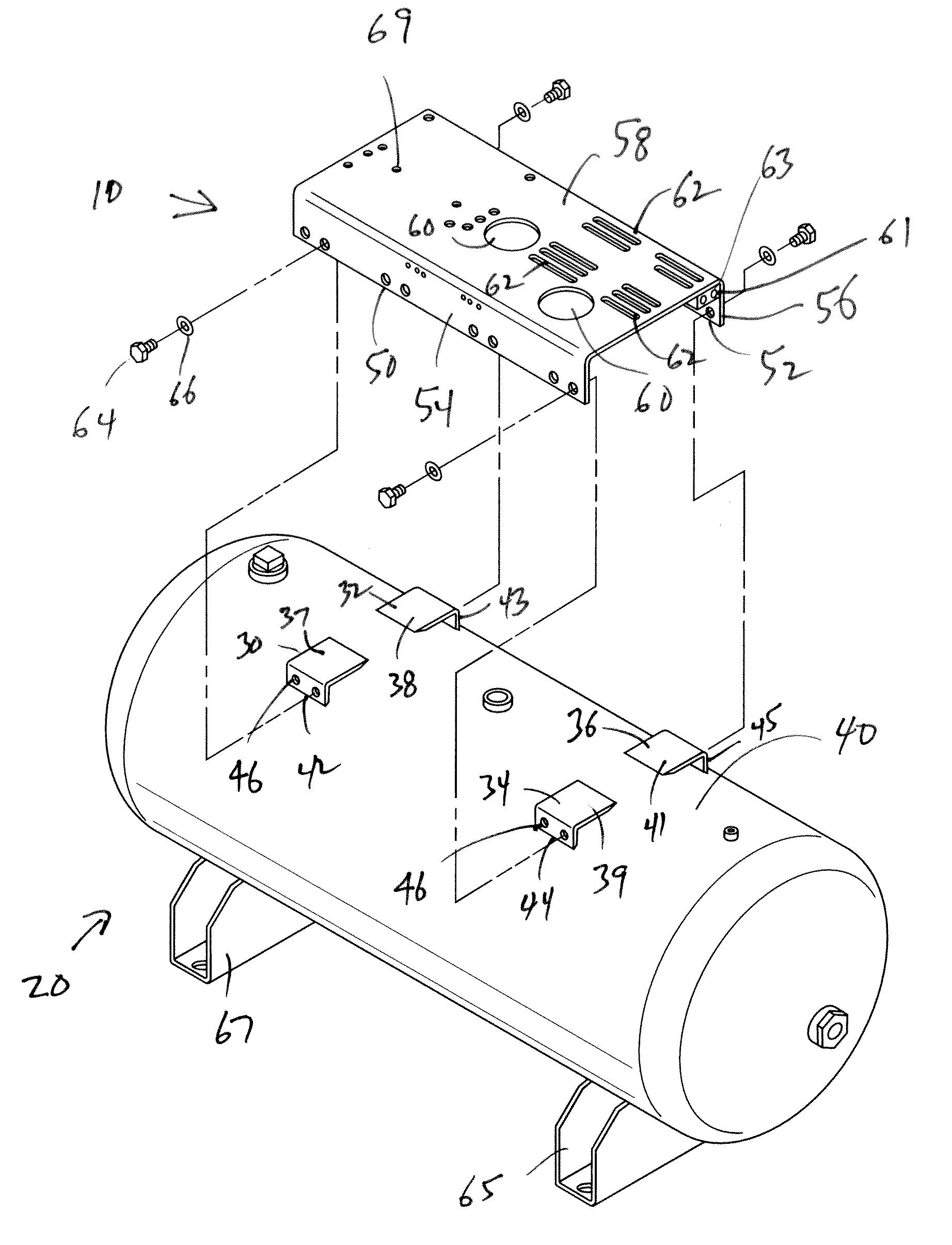
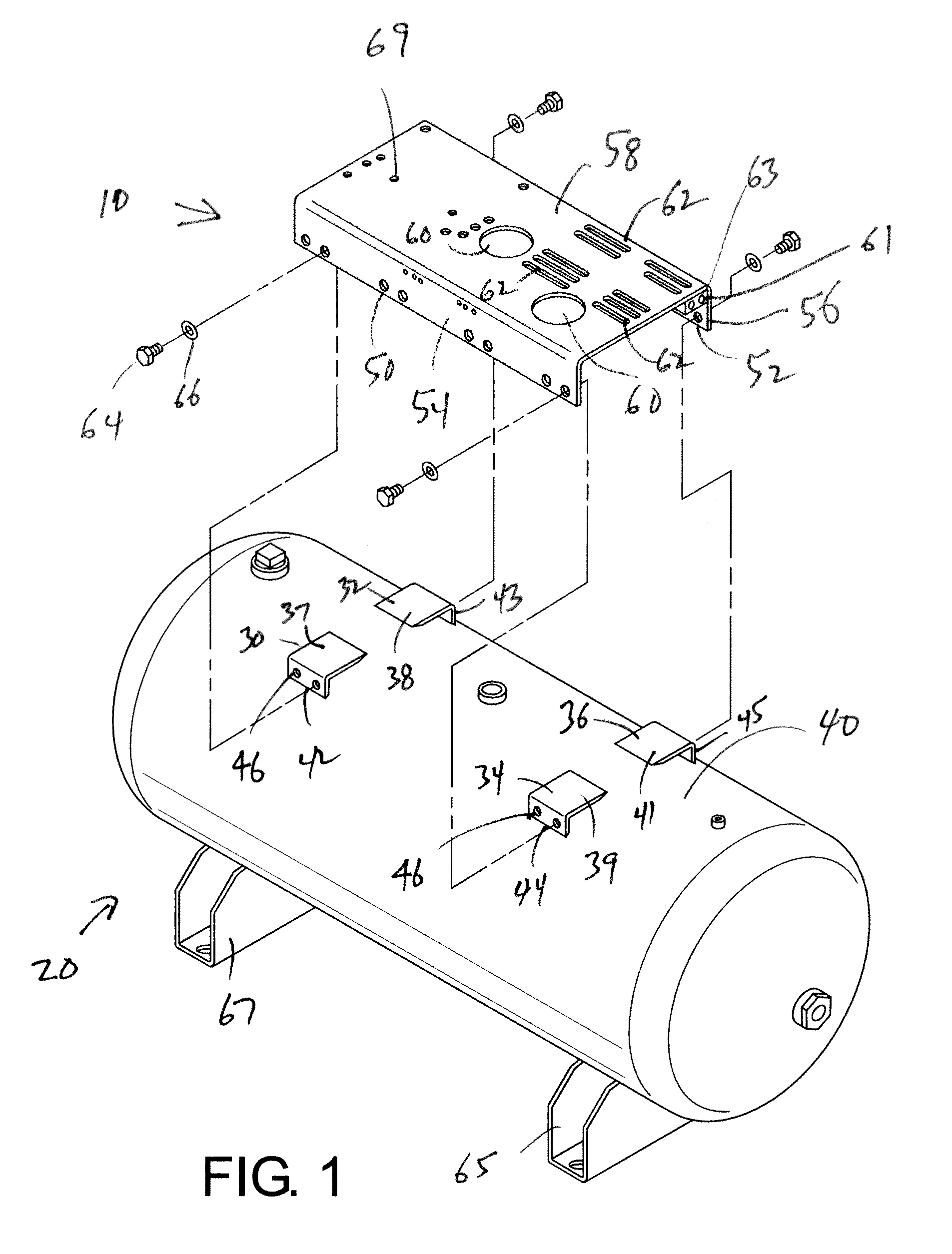
[0027]A cylindrical air receiver tank 20 is illustrated in FIG. 1 in accordance with a first embodiment of the present disclosure. The air receiver tank accommodates a belt driven air compressor, an electric or gasoline / diesel motor, and controls. The tank may be supported at one end by a pair of wheels or by legs. A handle may be attached to the legs to facilitate moving the portable air receiver tank. A gauge is used for indicating the pressure within the air receiving tank; a pressure regulator for controlling the pressure at a compressed air outlet; a gauge for indicating the gas pressure at the outlet; an outlet valve; and a pressure responsive switch for turning the motor on and off. The controls may be attached to a flange which is welded to an outlet opening in the air receiving tank.

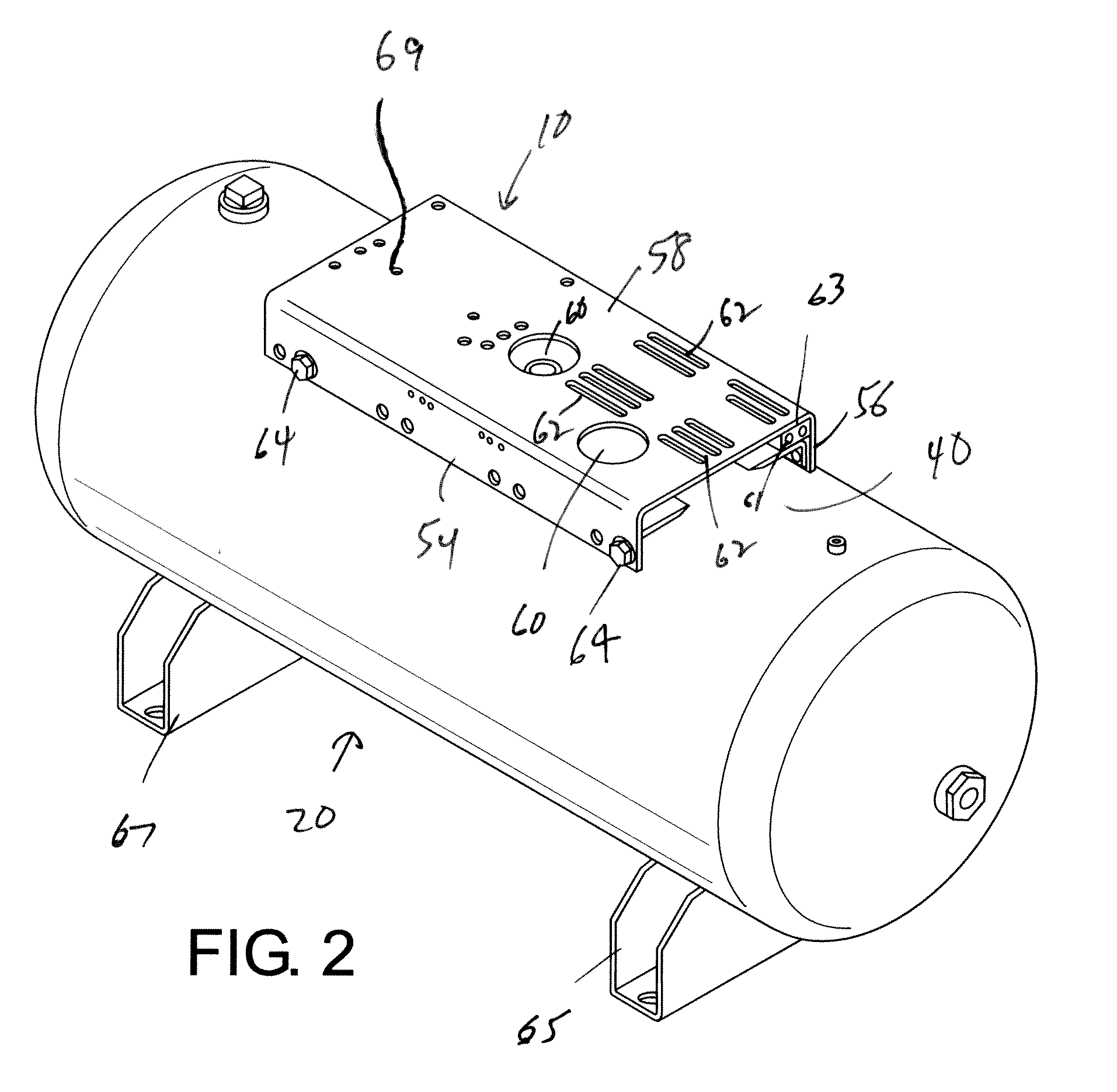
[0028]Referring specifically now to FIGS. 1 and 2, a horizontal simplex mounting plate 10 is bolted or otherwise secured to a top surface 40 of a horizontal air receiving tank 20. The mounting p...


PUM


Abstract

An air receiver tank and removable mounting plate assembly includes an air receiver tank having at least one mounting bracket secured thereto for removably mounting a mounting plate, wherein the bracket has holes. A mounting plate includes a top wall and first and second side walls extending from the top wall; wherein each of the first and second side walls includes holes. The mounting plate is removably secured to the air receiver tank via a plurality of fasteners received by the holes of the mounting brackets and corresponding holes of the mounting plate.

Description

CLAIM OF PRIORITY[0001]This application claims priority from Provisional application Ser. No. 61 / 172,953 filed on Apr. 27, 2009, which is incorporated herein by reference.BACKGROUND OF THE DISCLOSURE[0002]This disclosure relates to a mounting mechanism for an air compressor and drive motor on an air receiving tank and more particularly to a removable mounting plate or base for mounting a motor or a compressor to an upper surface of an air receiver tank in either a vertical or horizontal orientation.[0003]Portable and stationary air compressors are used for many applications, including operating pressure feed tanks, spray guns, caulking guns, air brushes, sand blasters, pneumatic tools, tire inflaters, etc. Air compressors for these applications generally include a cylindrical air receiving tank, a belt-driven air compressor, and an electric motor or gasoline / diesel engine defined as the driver. In existing air compressors, a mounting platform typically is permanently welded either t...

Claims


Application Information

Patent Timeline
IPC IPC(8): F16L3/00
CPCF04B35/06F04B41/02F04B39/14Y10T137/7039
Inventor STOPKA, BRIAN
Owner CURTIS TOLEDO
Why Eureka
Try Eureka