
Multi-chip stacked package

Active Publication Date: 2010-10-28
POWERTECH TECHNOLOGY
View PDF2 Cites 20 Cited by
  • Summary
  • Abstract
  • Description
  • Claims
  • Application Information

AI Technical Summary

Benefits of technology

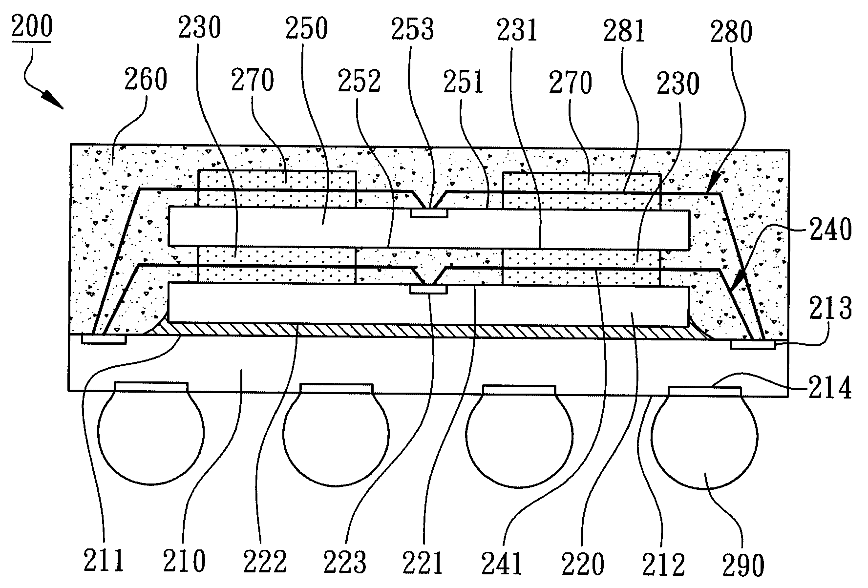
[0007]The main purpose of the present invention is to provide a multi-chip stacked package to effectively secure the bonding wires electrically connecting the stacked chips under limited component numbers and package thickness and to avoid bonding wires collapse and deformation as the conventional stacked package without trapped bubbles inside the die-attaching components.
[0008]The second purpose of the present invention is to provide a multi-chip stacked package to modify the loop heights of the bonding wires extending between stacked chips and to fasten the bonding wires in advance to increase the horizontal length without increasing the total package thickness to achieve lower cost with simplified processes.

Problems solved by technology

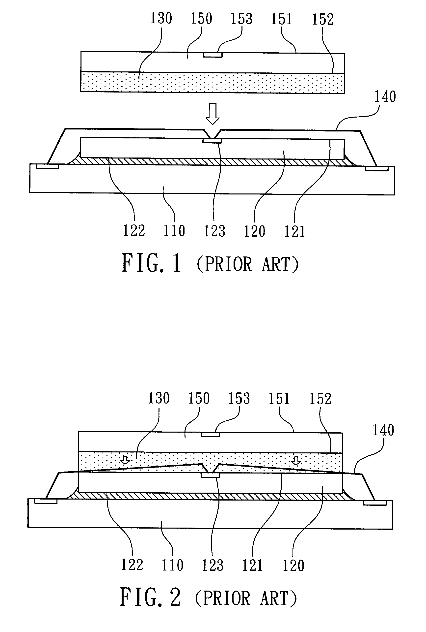
However, the length of bonding wires increases when stacking more chips, the risk of wire sweeping will also increase causing most common failure mode of electrical short in this multi-chip stacked package.
However, the bonding wires 140 are collapsed and deformed under the die-bonding pressure from the die-attaching material 130 to directly contact with the first active surface 121 of the first chip 120 leading to poor packaging quality, more the worse, leading to electrical short between the adjacent bonding wires 140 and air gap between the chips 120 and 150 causing lower packaging yield.
Even with the extended curing time, the center of the die-attaching material 130 still can not be fully cured leading to chip peeling issues due to uneven uniformity of curing level.
However, the pattern of the top die-attaching layer is different from the one of the bottom die-attaching layer, therefore, the top die-attaching layer can not easily fill the central gap of the bottom die-attaching layer causing trapped bubbles leading to package reliability issues.
Furthermore, since the top die-attaching layer has to be pre-formed on the back surface of the top chip, extra components and process are needed where the height of the stacked package is also increased which can not meet the light, slim, thin, and small requirements of electronic products with lower cost.
Moreover, trapped bubbles in the die-attaching layer will become an issue.
However, for the disclosed method, another cushion member is needed leading to more complicated process with higher cost where the cushion member located at the peripheries of the chip will also hinder the exhaust of the volatile materials inside the die-attaching layer.

Method used


Image

  • Multi-chip stacked package
  • Multi-chip stacked package
  • Multi-chip stacked package

Examples


Embodiment Construction

[0019]With reference to the attached drawings, the present invention is described by means of the embodiment(s) below where the attached drawings are simplified for illustration purposes only to illustrate the structures or methods of the present invention by describing the relationships between the components and assembly in the present invention. Therefore, the components shown in the figures are not expressed with the actual numbers, actual shapes, actual dimensions, or with the actual ratio. Some of the dimensions or dimension ratios have been enlarged or simplified to provide a better illustration. The actual numbers, actual shapes, or actual dimension ratios can be selectively designed and disposed and the detail component layouts may be more complicated.

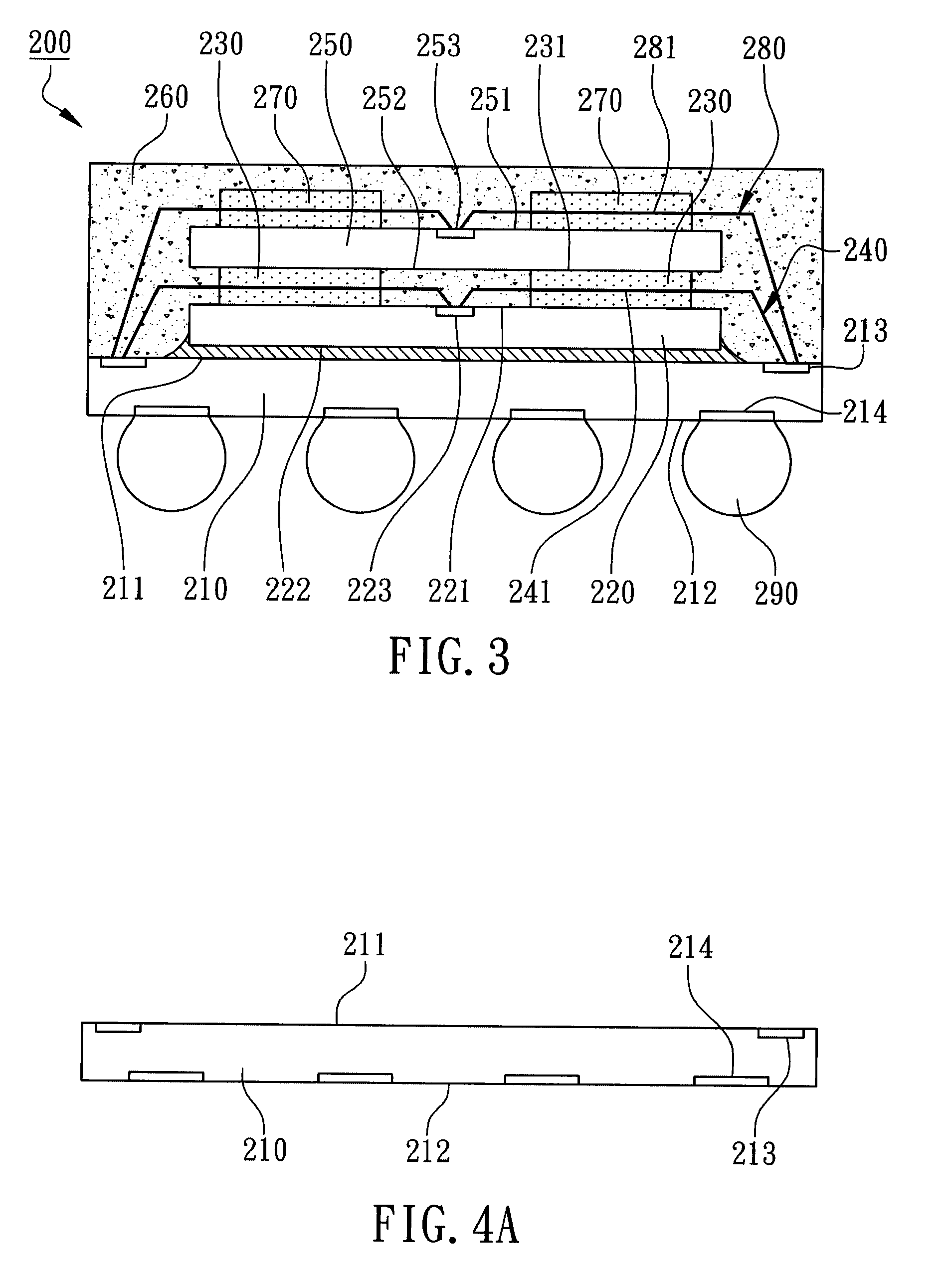
[0020]According to the first embodiment of the present invention, a multi-chip stacked package is illustrated in FIG. 3 for the cross-sectional view. The multi-chip stacked package 200 primarily comprises a chip carrier 210, a...


PUM


Abstract

A multi-chip stacked package primarily comprises a chip carrier, a first chip disposed on the chip carrier, a plurality of die-attaching bars, a second chip stacked on the first chip by the adhesion of the die-attaching bars, and a plurality of bonding wires electrically connecting the first chip to the chip carrier. The die-attaching bars are formed on the first chip in a specific pattern and have an adhesive surface away from the first chip for adhering the second chip. The bonding wires have a loop height lower than the adhesive surface in a manner that specific sections of the bonding wires are embedded in the corresponding die-attaching bar from the adhesive surface. Accordingly, the die-attaching bars can modify and fasten the bonding wires in advance to avoid collapse and deformation of the bonding wires during stacking of the second chip and encapsulating processes.

Description

FIELD OF THE INVENTION[0001]The present invention relates to semiconductor devices, and more particularly to multi-chip stacked packages.BACKGROUND OF THE INVENTION[0002]In a conventional multi-chip stacked package, a plurality of semiconductor chips are vertically stacked on a chip carrier with the active surfaces of the chips facing upward. Bonding wires are implemented to electrically connect the chips to the chip carrier. Comparing to back-to-back stacking, this multi-chip stacked package has the advantages of stacking more chips with better uniform bonding wire lengths connecting to different chips. However, the length of bonding wires increases when stacking more chips, the risk of wire sweeping will also increase causing most common failure mode of electrical short in this multi-chip stacked package. Film-Over-Wire (FOW) technology can be implemented to resolve wire sweeping issues by pre-encapsulating the middle sections of the bonding wires between the chips during chip sta...

Claims


Application Information

Patent Timeline
IPC IPC(8): H01L23/538
CPCH01L23/49816H01L24/29H01L24/32H01L24/48H01L24/73H01L24/91H01L25/0657H01L25/50H01L2224/32014H01L2224/32145H01L2224/32225H01L2224/45144H01L2224/48095H01L2224/48227H01L2224/484H01L2224/48599H01L2224/4899H01L2224/73265H01L2224/83856H01L2224/85203H01L2224/85207H01L2224/92247H01L2225/0651H01L2225/06575H01L2225/06593H01L2924/01005H01L2924/01013H01L2924/01029H01L2924/01079H01L2924/01082H01L2924/014H01L2924/15311H01L2224/2919H01L2924/01006H01L2924/01033H01L2924/0665H01L2224/29101H01L2924/00014H01L2924/00H01L2924/00012H01L24/45H01L2924/181H01L2224/05624H01L2224/05647
Inventor SU, TING-FENGCHEN, CHIEN-MING
Owner POWERTECH TECHNOLOGY
Learn More