Optical Source Assembly Suitable for Use as a Solar Simulator and Associated Methods

a technology of optical source assembly and solar simulator, which is applied in the direction of optical radiation measurement, instruments, lighting and heating apparatus, etc., can solve the problem that the old technology is no longer suitabl

Active Publication Date: 2010-10-28
THE BOEING CO
View PDF32 Cites 18 Cited by
  • Summary
  • Abstract
  • Description
  • Claims
  • Application Information

AI Technical Summary

Problems solved by technology

With the introduction of six junction solar cells, this old technology is no longer suitable.

Method used


Image

  • Optical Source Assembly Suitable for Use as a Solar Simulator and Associated Methods
  • Optical Source Assembly Suitable for Use as a Solar Simulator and Associated Methods
  • Optical Source Assembly Suitable for Use as a Solar Simulator and Associated Methods

Examples


Embodiment Construction

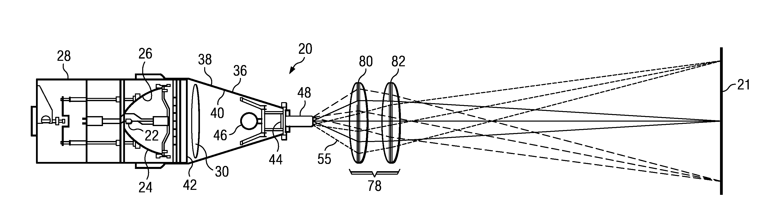
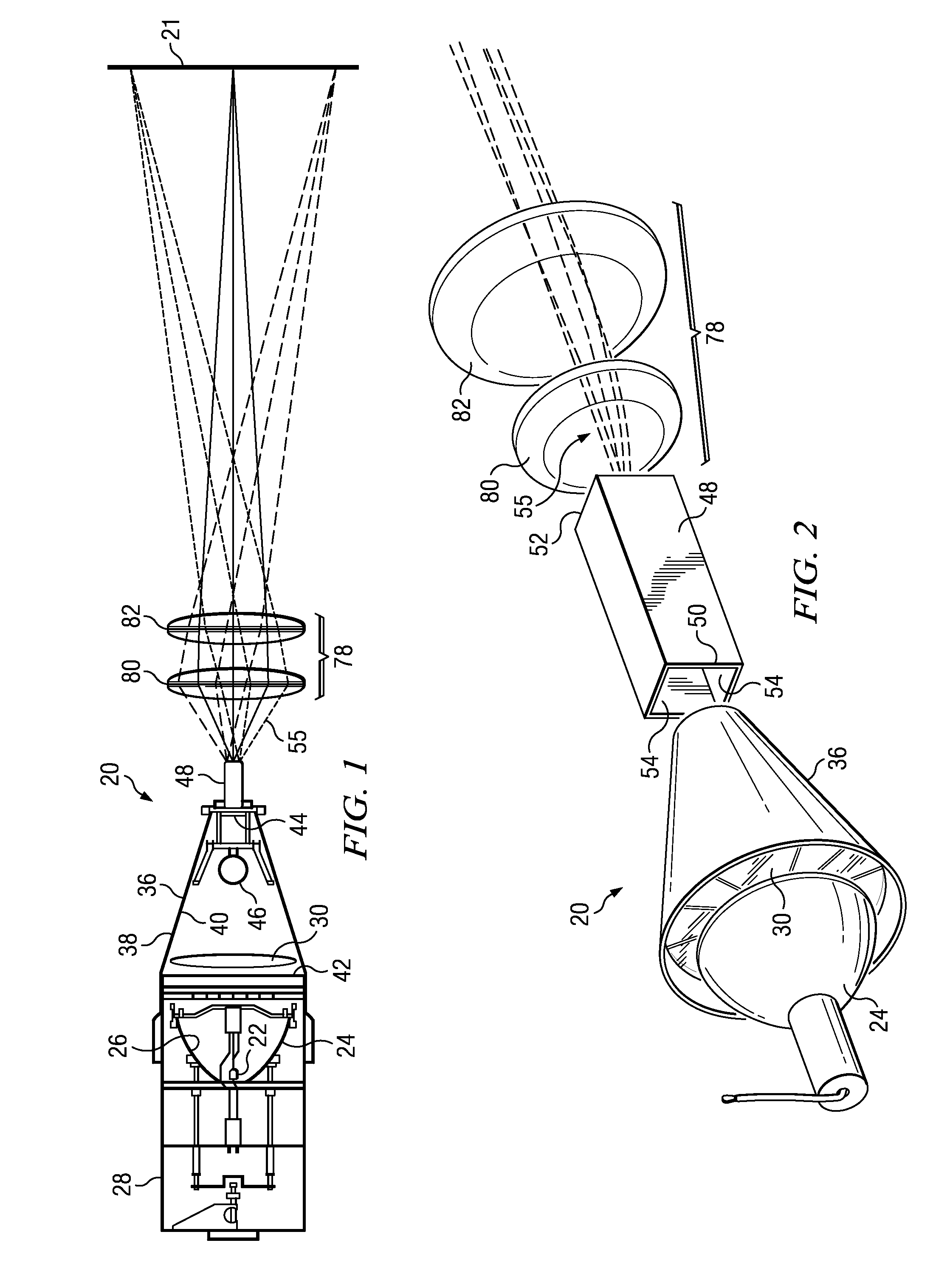
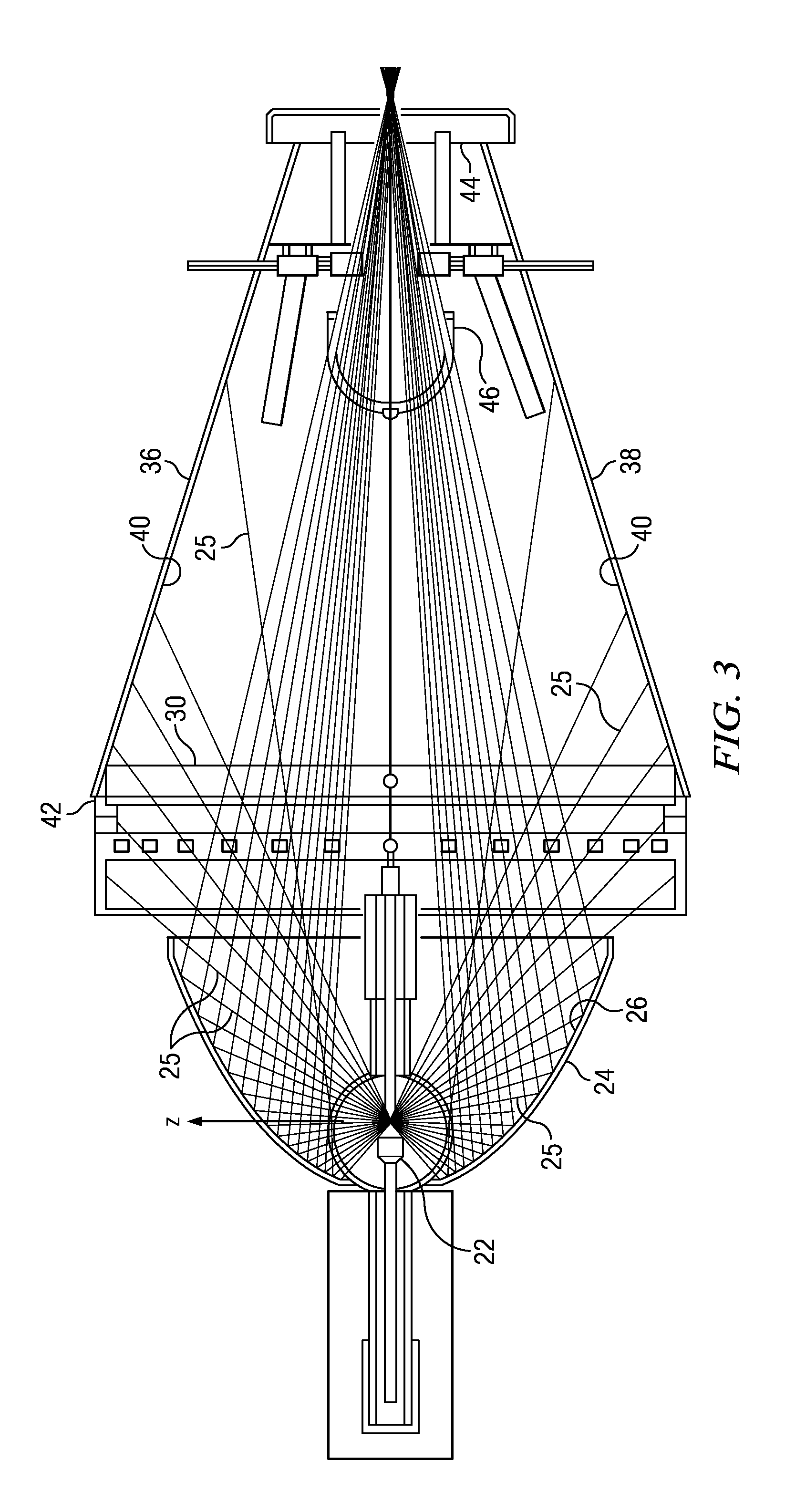
,” one will understand how the features of the present embodiments provide advantages, which include the ability to produce a spatially well balanced output beam, the ability to easily adjust the spectral characteristics of the output beam, the ability to image the output beam to a point in space where the test sensor / solar cell is located, and the ability to control the range of angles of incidence on the test sensor / solar cell.

[0007]One illustrative embodiment comprises an apparatus. The apparatus may have a light source configured to generate light, a reflector configured to collect the light and direct the light in a desired direction, and a spectral filter assembly configured to receive the light from the reflector. The spectral filter assembly may have a stationary frame, and a plurality of filter elements supported by the stationary frame, filter elements of the plurality of filter elements simultaneously filtering a desired quantity of light within a wavelength band to provi...


PUM


Abstract

An apparatus may have a light source configured to generate light, a reflector configured to collect the light and direct the light in a desired direction, a spectral filter assembly configured to receive the light from the reflector. The spectral filter assembly may have a stationary frame and a plurality of filter elements supported by the stationary frame. Filter elements of the plurality of filter elements may simultaneously filter a desired quantity of light within wavelength band to provide a filtered output light beam. A homogenizer may be configured to receive the filtered output light beam and produce a homogenized light beam having a substantially uniform irradiance distribution across a cross-section of the homogenized light beam.

Description

RELATED APPLICATION[0001]This application is a continuation-in-part of patent application U.S. Ser. No. 12 / 128,386, filed May 28, 2008, entitled “Optical Source Assembly Suitable For Use as a Solar Simulator and Associated Methods”, status pending, which, in turn, claims priority to provisional application Ser. No. 61 / 051,786, filed on May 9, 2008, the entire contents of which are hereby incorporated by reference.BACKGROUND INFORMATION[0002]1. Field:[0003]The present disclosure relates to testing of solar cells and other optical sensors.[0004]2. Background:[0005]Many optical sensors, particularly solar cells, need to be tested at various stages in the production cycle to assure performance and reliability. With solar cells made using older technologies, it was sufficient to test the cells with a properly shaped, spatially uniform beam on the solar cells. For example, it was not of great importance to ensure that factors such as spectral content and range of incident angles of the li...

Claims


Application Information

Patent Timeline
Patent Type & Authority Applications(United States)
IPC IPC(8): F21V9/02F21V9/00
CPCF21S8/006G01J1/04G01J1/0422G01J1/0488F21V9/02G01J2001/0481G02B27/0983G02B27/0994F21V14/08G01J1/08
Inventor JUNGWIRTH, DOUGLAS R.EIGLER, LYNNE C.
Owner THE BOEING CO
Why Eureka
Try Eureka