
Amplifier circuit audio circuit and electronic device

a technology of amplifier circuit and audio circuit, applied in the direction of stereophonic circuit arrangement, low frequency amplifier, electrical transducer, etc., can solve the problems of circuit b>10/b> consuming a relatively large amount of power, occupying a relatively large area, and requiring an accurate determination

Active Publication Date: 2010-10-28
NXP USA INC
View PDF6 Cites 3 Cited by
  • Summary
  • Abstract
  • Description
  • Claims
  • Application Information

AI Technical Summary

Problems solved by technology

The large value coupling capacitors are expensive and occupy a relatively large area.
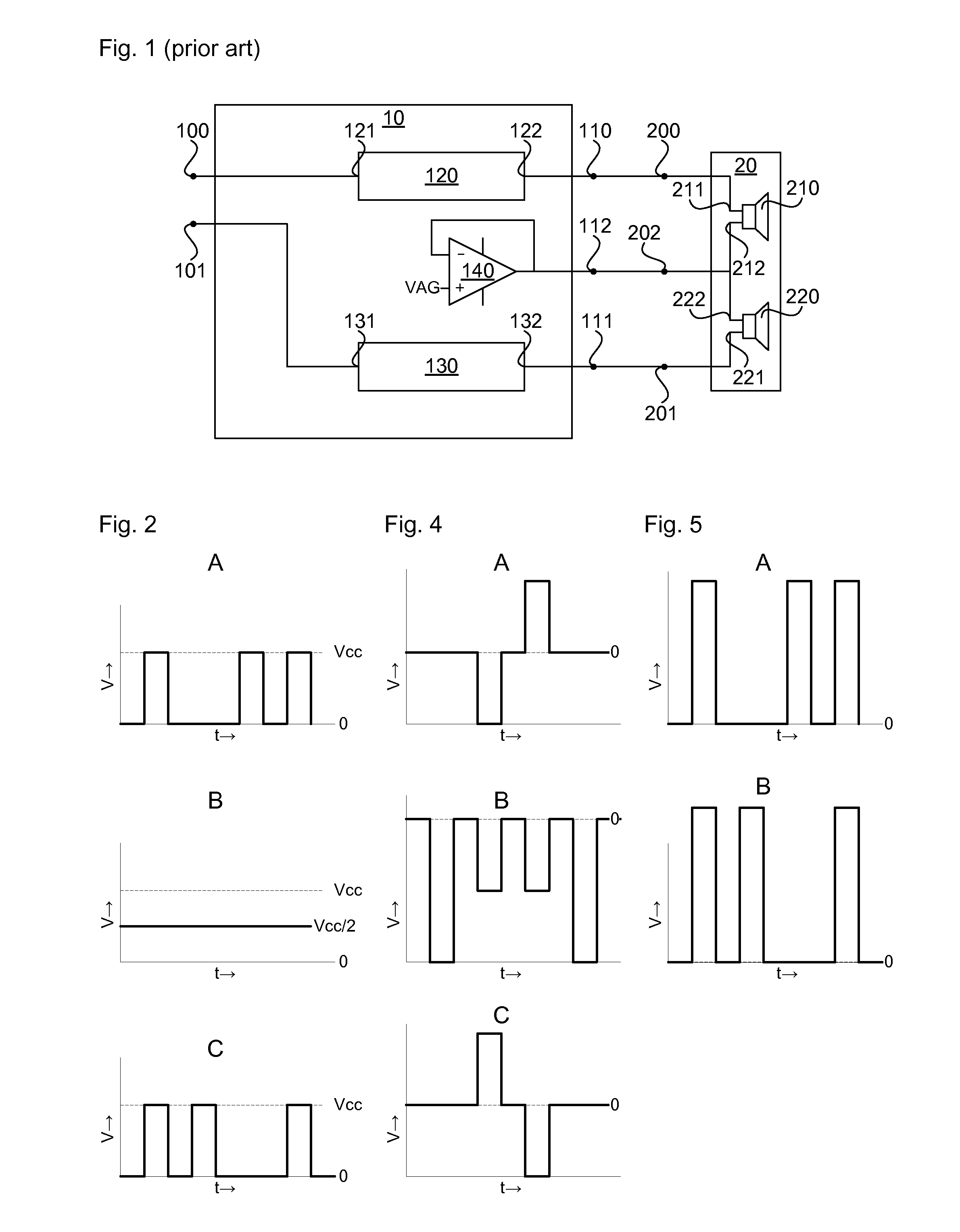
However, although the shown prior art circuit allows the use of a conventional headset with a three pole plug without requiring coupling capacitors between the amplifier circuit 10 and the headset 20, a disadvantage of the prior art circuit is that the circuit 10 requires an accurate determination of the common mode in order to set amplifier gain voltage VAG.
Furthermore, the circuit 10 consumes a relatively large amount of power and has a relatively large footprint because of the operational amplifier 140.

Method used


Image

  • Amplifier circuit audio circuit and electronic device
  • Amplifier circuit audio circuit and electronic device
  • Amplifier circuit audio circuit and electronic device

Examples


Embodiment Construction

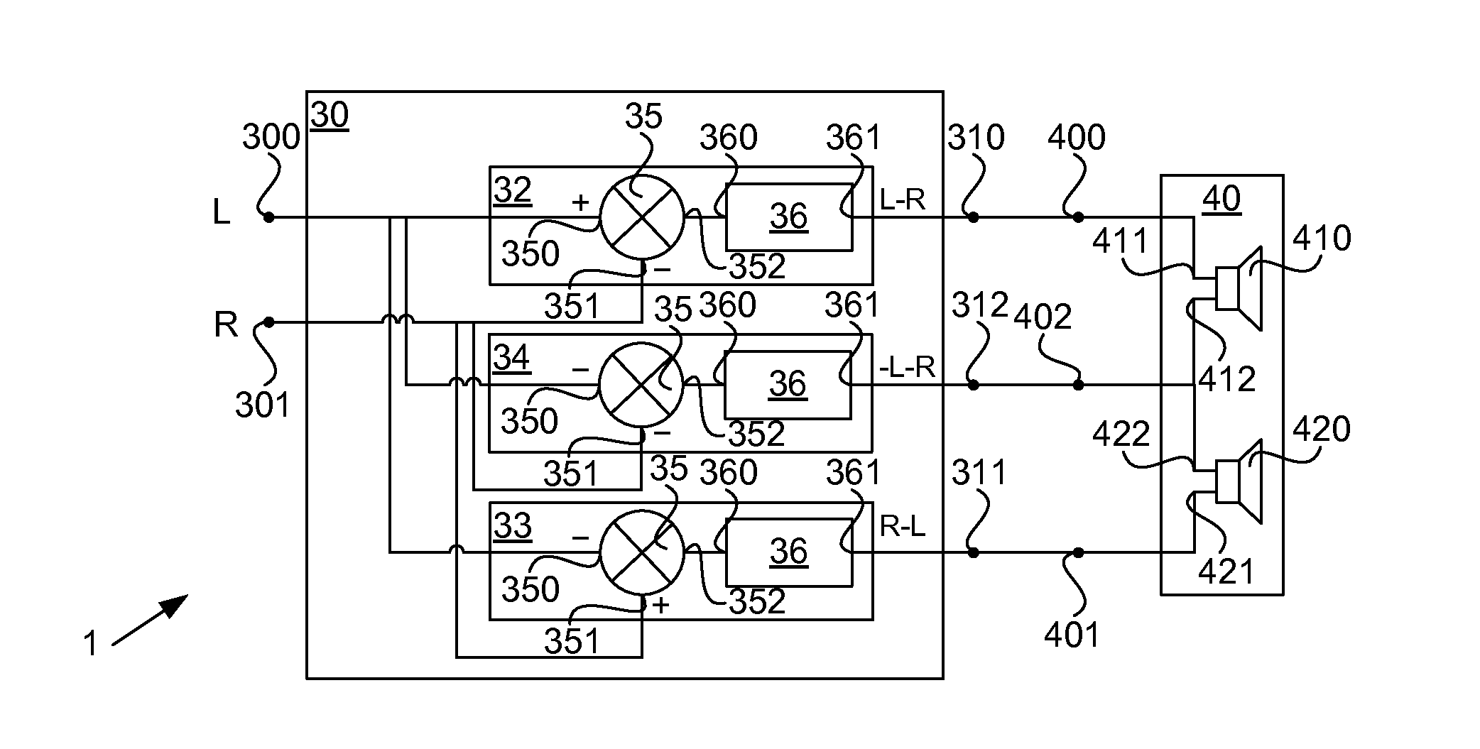
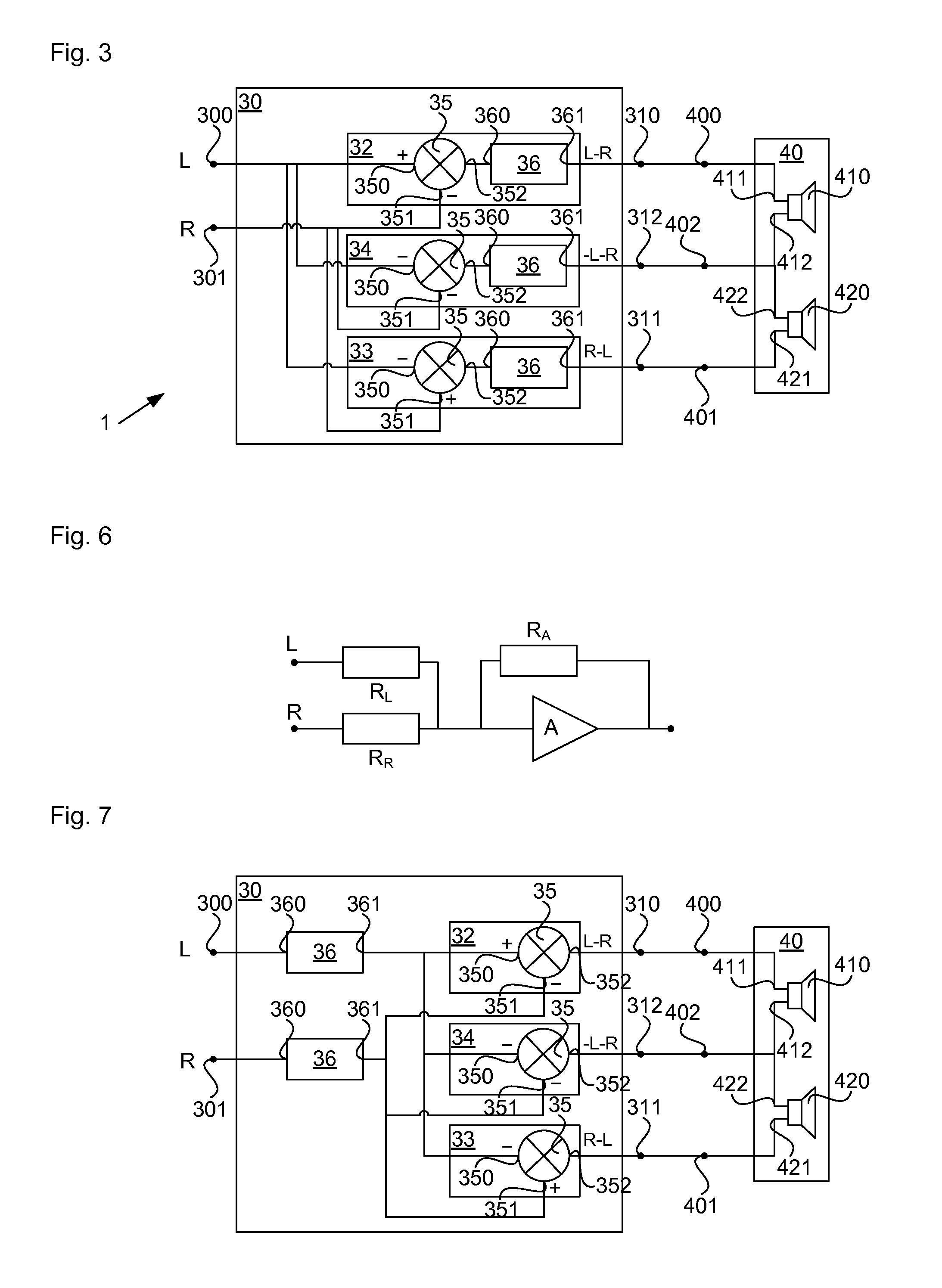
[0019]Referring FIG. 3, an example of an embodiment of an amplifier circuit 30 is shown therein. The amplifier circuit 30 may, as shown, include a first input 300 for receiving first input signal and a second input 301 for receiving a second signal. As shown in FIG. 3, the amplifier circuit 30 may include a first amplifier section 32, a second amplifier section 33, as well as a common mode section 34.

[0020]In the following, the amplifier circuit 30 will be elucidated further using the example of a stereo audio signal which comprises a left channel signal which is to be outputted at a loudspeaker at a first side and a right channel signal which is to be outputted at a loudspeaker at a second side. The first input signal will be referred to as the left channel signal, the second input signal as the right channel signal, the first input will be referred to as the left channel input 300 and the second input will be referred to as the right channel input 301. The first amplifier section ...


PUM


Abstract

An amplifier circuit which, includes a first input for receiving a first input signal and a second input for receiving a second input signal. A first amplifier section is connected to the first input and the second input is present. The first amplifier section can combine the first signal and the second signal into a first combined signal, the first amplifier being connected to a first output, for outputting the first combined signal. A second amplifier section is connected to the first input and the second input, for combining the first signal and the second signal into a second combined signal, the second amplifier being connected to a second output, for outputting the second combined signal. A common mode section is connected to the first input and the second input, for generating a common mode signal based on a combination of the first signal and the second signal and outputting the common mode signal at a common output connected to the common mode amplifier. The first combined signal, the second combined signal and the common mode signal satisfy the condition that combining the first combined signal and the common mode signal results in a signal with an amplitude proportional to the amplitude of the first input signal and combining the second combined signal and the common mode signal results in a signal with an amplitude proportional to the amplitude of the second input signal.

Description

FIELD OF THE INVENTION[0001]This invention relates to an amplifier circuit, to an audio circuit, and to an electronic device.BACKGROUND OF THE INVENTION[0002]Amplifier circuits are generally known in the art and used, for example, to provide amplified signals to the loudspeakers of a headset. For example, amplifier circuits are known which can be connected to a headset via a three or four pole jacket and plug configuration. Between the signal outputs of the amplifier circuit and the headset, large value coupling capacitors are typically present. The large value coupling capacitors are expensive and occupy a relatively large area.[0003]Amplifier circuits in which the need for the large value coupling capacitors is obviated are known. Referring to FIG. 1 of the accompanying drawings, an amplifier circuit 10 as is known from the prior art is shown. The amplifier circuit 10 is connected to a headset 20 which comprises two loudspeakers 210,220 each with respective negative and positive c...

Claims


Application Information

Patent Timeline
IPC IPC(8): H03F99/00H03F3/68
CPCH03F3/181H03F3/217H03F3/68H04R2460/03H03F2201/3206H04R5/04H03F2200/03
Inventor ODDOART, LUDOVICTRAUTH, GERHARDCHARLET, JEAN-LUC
Owner NXP USA INC
Learn More