Over-Parameterized Variational Optical Flow Method

a variational optical flow and optical flow technology, applied in image data processing, instruments, character and pattern recognition, etc., can solve the problem of remaining challenging in computer vision field, and achieve the effect of richer means for optical flow representation

Inactive Publication Date: 2010-10-28
TECHNION RES & DEV FOUND LTD
View PDF8 Cites 34 Cited by
  • Summary
  • Abstract
  • Description
  • Claims
  • Application Information

AI Technical Summary

Benefits of technology

[0006]It is an object of the present invention to represent the optical flow vector at each pixel by different coefficients of the same motion model in a variational framework. Such a grossly over-parameterized representation has the advantage that the smoothness term may now penalize deviations from the motion model instead of directly penalizing the change of the flow. For example, in an affine motion model, if the flow in a region can be accurately represented by an affine model, then in this region there will be no flow regularization penalty, while in the usual setting there is a cost resulting from the changes in the flow induced by the affine model. This over-parameterized model thereby offers a richer means for optical flow representation. For segmentation purposes, the over-parameterization has the benefit of making segmentation decisions in a more appropriate space (e.g. the parameters of the affine flow) rather than in a simple constant motion model space. The work of Ju et al. (1996) is related to our methodology, they used local affine models to describe the motion in image regions imposing spatial smoothness on the affine parameters between neighboring patches. The key and conceptually very important difference is that, in our approach, the model is represented at the pixel level which makes the problem over-parameterized while the patch size chosen in (Ju et al. 1996) makes it under-parameterized and requires the choice of a neighborhood size.

Problems solved by technology

Despite much research effort invested in addressing optical flow computation it remains a challenging task in the field of computer vision.

Method used


Image

  • Over-Parameterized Variational Optical Flow Method
  • Over-Parameterized Variational Optical Flow Method
  • Over-Parameterized Variational Optical Flow Method

Examples


Embodiment Construction

[0032]In the following detailed description of various embodiments, reference is made to the accompanying drawings that form a part thereof, and in which are shown by way of illustration specific embodiments in which the invention may be practiced. It is understood that other embodiments may be utilized and structural changes may be made without departing from the scope of the present invention.

2. OVER-PARAMETRIZATION MODEL

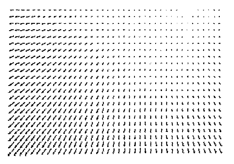
[0033]We propose to represent the optical flow (u(x, y, t), v(x, y, t)) by the general over-parameterized space-time model

u(x,y,t)=∑i=1nAi(x,y,t)φi(x,y,t),(1)v(x,y,t)=∑i=1nAi(x,y,t)ηi(x,y,t),

[0034]where, Φi(x, y, t) and ηi(x, y, t), i=1, . . . , n are n basis functions of the flow model, while the Ai are space and time varying coefficients of the model. This is an obviously heavily over-parameterized model since for more than two basis functions, there are typically many ways to express the same flow at any specific location. This redundancy however will be adequa...


PUM


Abstract

An optical flow estimation process based on a spatio-temporal model with varying coefficients multiplying a set of basis functions at each pixel. The benefit of over-parameterization becomes evident in the smoothness term, which instead of directly penalizing for changes in the optic flow, accumulates a cost of deviating from the assumed optic flow model. The optical flow field is represented by a general space-time model comprising a selected set of basis functions. The optical flow parameters are computed at each pixel in terms of coefficients of the basis functions. The model is thus highly over-parameterized, and regularization is applied at the level of the coefficients, rather than the model itself. As a result, the actual optical flow in the group of images is represented more accurately than in methods that are known in the art.

Description

FIELD OF THE INVENTION[0001]The present invention relates in general to image processing and in particular to a method and system for determining optical flow.BACKGROUND OF THE INVENTION[0002]Optical flow is a concept which approximates the motion of objects within a visual representation. Optical flow is the velocity field which warps one image into another (usually very similar) image. Optical flow techniques are based on the idea that the same physical point on an object in the scene is captured by the camera in corresponding points in the two images preserving certain image properties such as brightness, the gradient vector, etc.[0003]Optical flow computations are central to many image processing applications that deal with groups of similar images. For example, image sequence compression algorithms commonly use optical flow parameters to represent images compactly in terms of changes relative to preceding or succeeding images in the sequence. Optical flow parameters are also us...

Claims


Application Information

Patent Timeline
Patent Type & Authority Applications(United States)
IPC IPC(8): G06K9/00
CPCG06T7/2066G06T7/269
Inventor NIR, TALBRUCKENSTEIN, ALFRED M.KIMMEL, RON
Owner TECHNION RES & DEV FOUND LTD
Why Eureka
Try Eureka