Apparatus, method and computer program for applying energy to an object

a technology of energy application and apparatus, applied in the field of apparatus, a computer program for applying energy to an object, can solve the problems of inaccuracy in applying optical energy to the tissue, in particular, and achieve the effect of applying energy along a line more accurately

Inactive Publication Date: 2010-10-28
KONINKLIJKE PHILIPS ELECTRONICS NV
View PDF15 Cites 25 Cited by
  • Summary
  • Abstract
  • Description
  • Claims
  • Application Information

AI Technical Summary

Benefits of technology

[0005]It is an object of the present invention to provide an apparatus, a method and a computer program for applying energy to an object, which allow applying energy along a line more accurately.

Problems solved by technology

This leads to an inaccurate application of optical energ

Method used


Image

  • Apparatus, method and computer program for applying energy to an object
  • Apparatus, method and computer program for applying energy to an object
  • Apparatus, method and computer program for applying energy to an object

Examples


Embodiment Construction

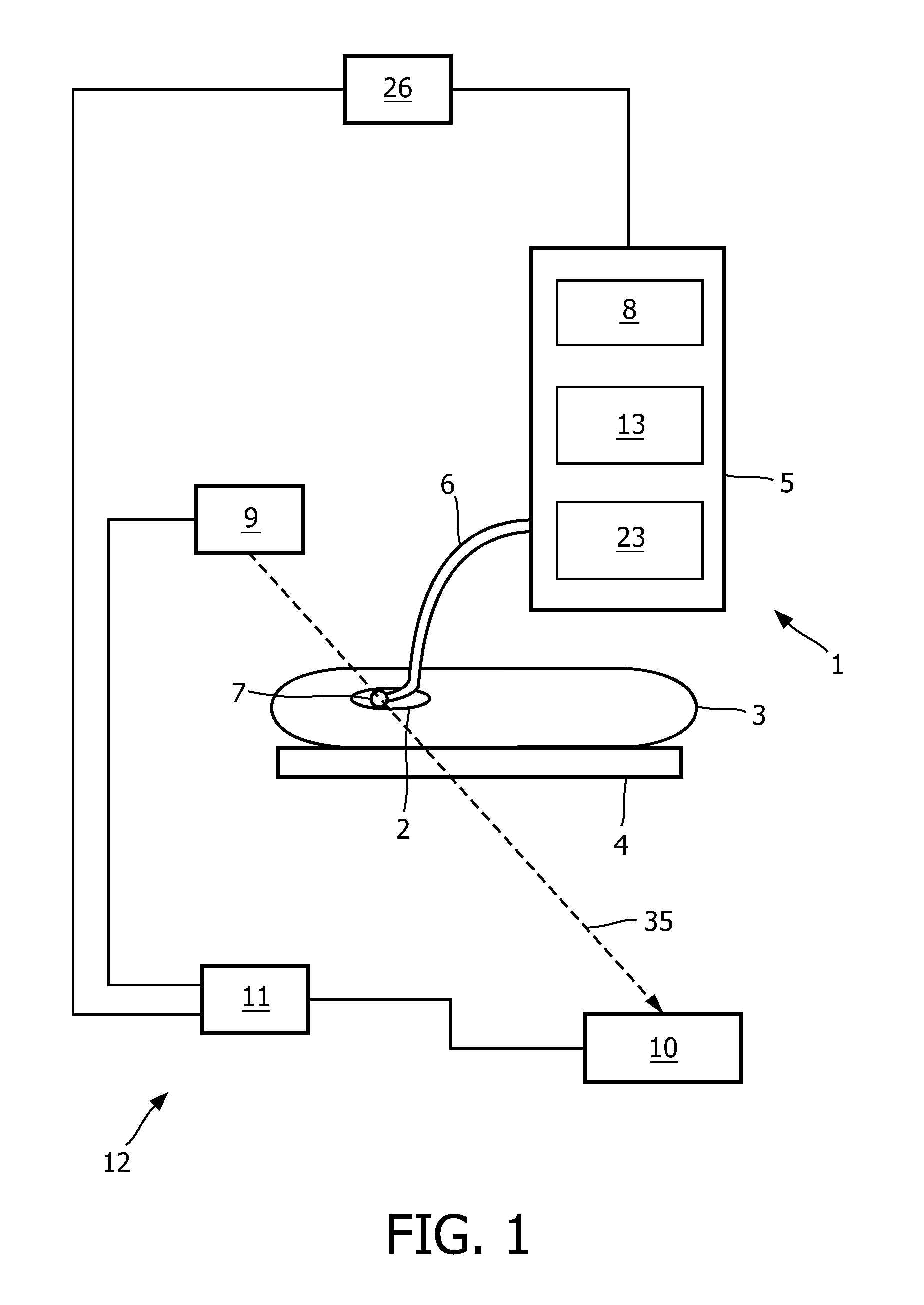
[0045]FIG. 1 shows an apparatus 1 for applying energy to an object. The apparatus 1 comprises a tube, in this embodiment, a catheter 6, and an arrangement 7, which comprises energy emission locations and sensing locations. The arrangement 7 is connected to a first control unit 5 via the catheter 6. The catheter 6 with the arrangement 7 can be introduced into an object 2, which is, in this embodiment, a heart of a patient 3 located on a patient table 4, wherein the catheter 6 is steered and navigated to the heart chamber by build-in guiding means (not shown), which can be controlled from outside by a guiding control unit 23. In another embodiment, the catheter can, for example, be steered and navigated by using guiding wires to guide the catheter passively into the heart. Also the guiding wires can be controlled by the guiding control unit 23.

[0046]During introduction of the arrangement 7 and the catheter 7 into the object 2 an imaging device 12, which is in this embodiment, a fluoro...


PUM

PropertyMeasurementUnit
Energyaaaaaaaaaa

Abstract

The present invention relates to an apparatus for applying energy to an object (2), wherein the apparatus comprises at least one combination element (36) for combining multiple energy applying elements (37) for applying energy to the object, wherein the combination element comprises an axis (60), around which the energy applying elements (37) are wound, wherein the energy applying elements (37) comprise energy emission locations arranged along a line.

Description

FIELD OF THE INVENTION[0001]The invention relates to an apparatus, a method and a computer program for applying energy to an object. The invention relates further to a combination element for combining multiple energy applying elements for applying energy to the object for use in the apparatus and a method for producing the apparatus.BACKGROUND OF THE INVENTION[0002]An apparatus for applying energy to an object is, for example, used in the field of interventional treatment of atrial fibrillation, wherein cardiac tissue is denaturized by thermal therapy. Radio Frequency energy is applied to the cardiac tissue using a catheter and thermal energy is generated due to resistive losses in the tissue of the myocardium. The heated muscle cells in the cardiac tissue die off and lose their biological function, which can be measured by an increase in the tissue impedance.[0003]U.S. Pat. No. 5,830,209 discloses a laser catheter comprising multiple optical fibers for applying optical energy to t...

Claims


Application Information

Patent Timeline
IPC IPC(8): A61B18/14A61B18/24H01F7/06
CPCA61B5/6858A61B2018/2244A61B18/1485A61B2017/00022A61B2018/00214A61B18/1492A61B18/24Y10T29/49071A61B2018/00898A61B2018/2216A61B5/015A61B2017/00057A61B18/1815A61B5/0084A61B2017/00026A61B2018/00267
Inventor MIHAJLOVIC, NENADKAHLERT, JOACHIM
Owner KONINKLIJKE PHILIPS ELECTRONICS NV
Why Eureka
Try Eureka