Deflection system for a particle beam device

a particle beam and deflector technology, applied in the field of particle beam apparatus and device, can solve the problems of large energy-corrected deflector aperture, large distance between deflector plate and coil, and particle beam dispersion, etc., to achieve high energy spread, low vacuum, and easy production

Inactive Publication Date: 2006-09-12
AKT ELECTRON BEAM TECH
View PDF11 Cites 5 Cited by
  • Summary
  • Abstract
  • Description
  • Claims
  • Application Information

AI Technical Summary

Benefits of technology

[0018]The inventive particle beam apparatus, the device and the inventive method allow for an energy-corrected deflection of a particle beam by a predetermined deflection angle without the above-mentioned disadvantages. According to the invention, the corrector can exert forces to the incoming particle beam which changes the direction of the charged particles depending on their energy in such a way that the energy-depending deflection of the deflector focuses them. In this manner, the corrector can compensate an energy-depending dispersion of the particle beam that the deflector without corrector would otherwise inflict on the particle beam.
[0051]If the deflector includes a second electric multipole, the first and the second electric multipoles are aligned with respect to each other in such a way that they can generate electric fields at the particle beam which are orientated parallel or antiparallel with respect to each other. This way, an energy correcting deflection can be conducted in advantageous manner.

Problems solved by technology

An energy-depending dispersing of a particle beam, also called chromatic aberration or “Farbfehler”, in often undesired since it may limit the spatial resolution of the particle beam apparatuses, particularly electron microscopes, apparatuses for electron- or ion-lithography and display apparatuses.
The complexity for building particle beam apparatuses with energy correcting deflectors that superimpose electric and magnetic fields is considerable, since the fields for such deflectors must be higher than for deflectors without energy correction.
A large aperture for the energy-corrected deflector, however, requires large deflection plate distances and large coil distances.
This leads to a further enlargement or the coils, the voltages and / or the coil currents of the deflector, which in turn further increases the volume and further limits the possible usage.
A short working distance can cause considerable problems if further components, like a deflector, have to be mounted between the objective lens and target surface.
With the limited space of a small-sized deflector, the possibility of equipping the deflector with energy-correcting components is limited.
The influence of the spherical or chromatic aberrations of the objective lens, however, is only an error of the second order, since the aberrations apply only to such charged particles whose energy deviates from the predetermined energy value.
The spatial resolution during structuring or sampling of the target surface is limited to a large extent by the focus area of the particle beam.
The disadvantage is that they generate particle beams with comparably high energy spread which is why, in this case, an energy corrected deflection is especially important.

Method used


Image

  • Deflection system for a particle beam device
  • Deflection system for a particle beam device
  • Deflection system for a particle beam device

Examples


Embodiment Construction

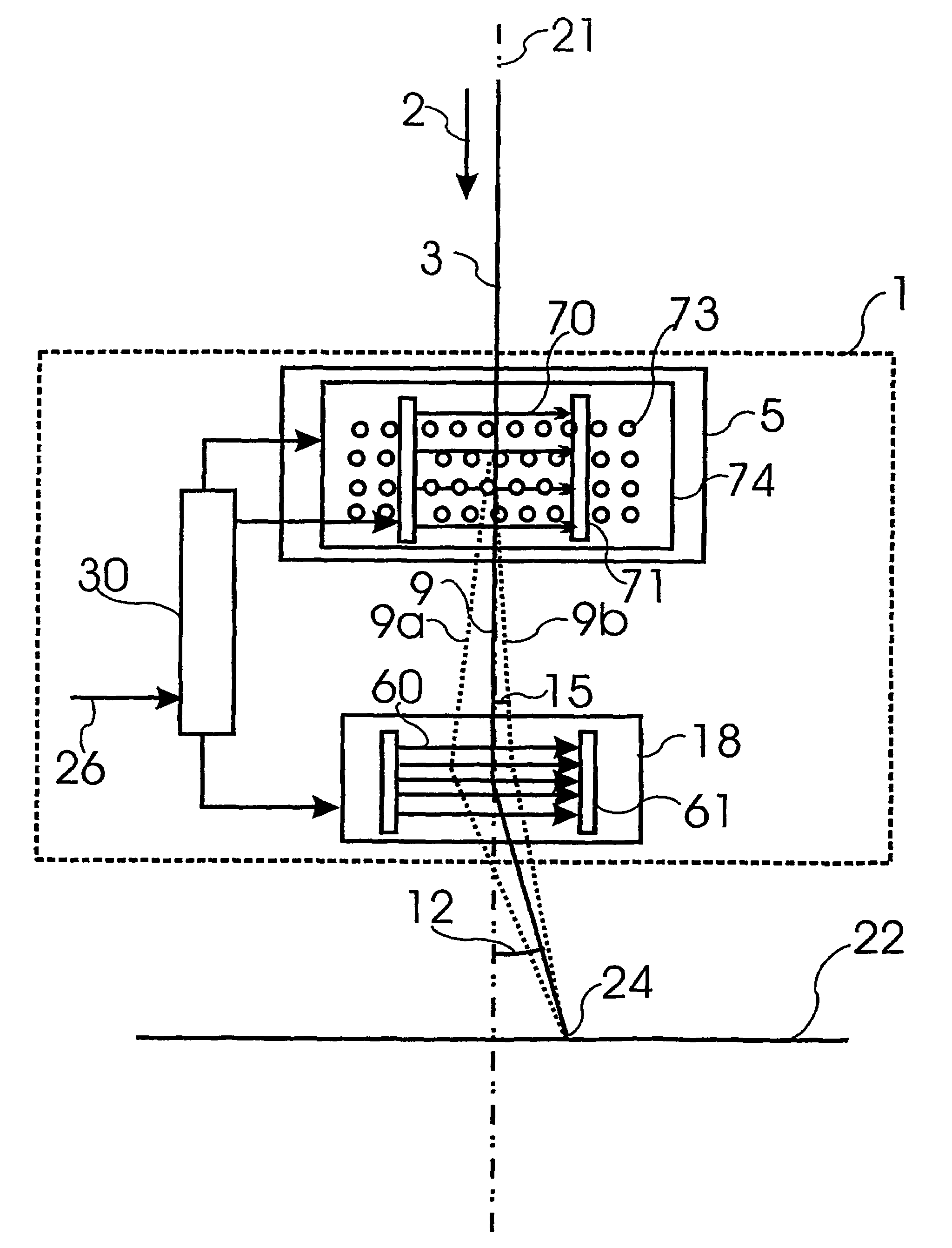
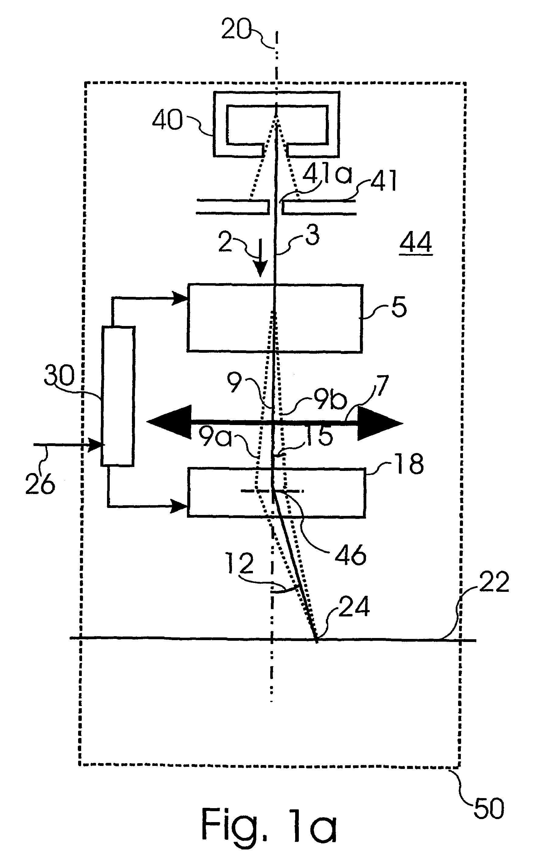
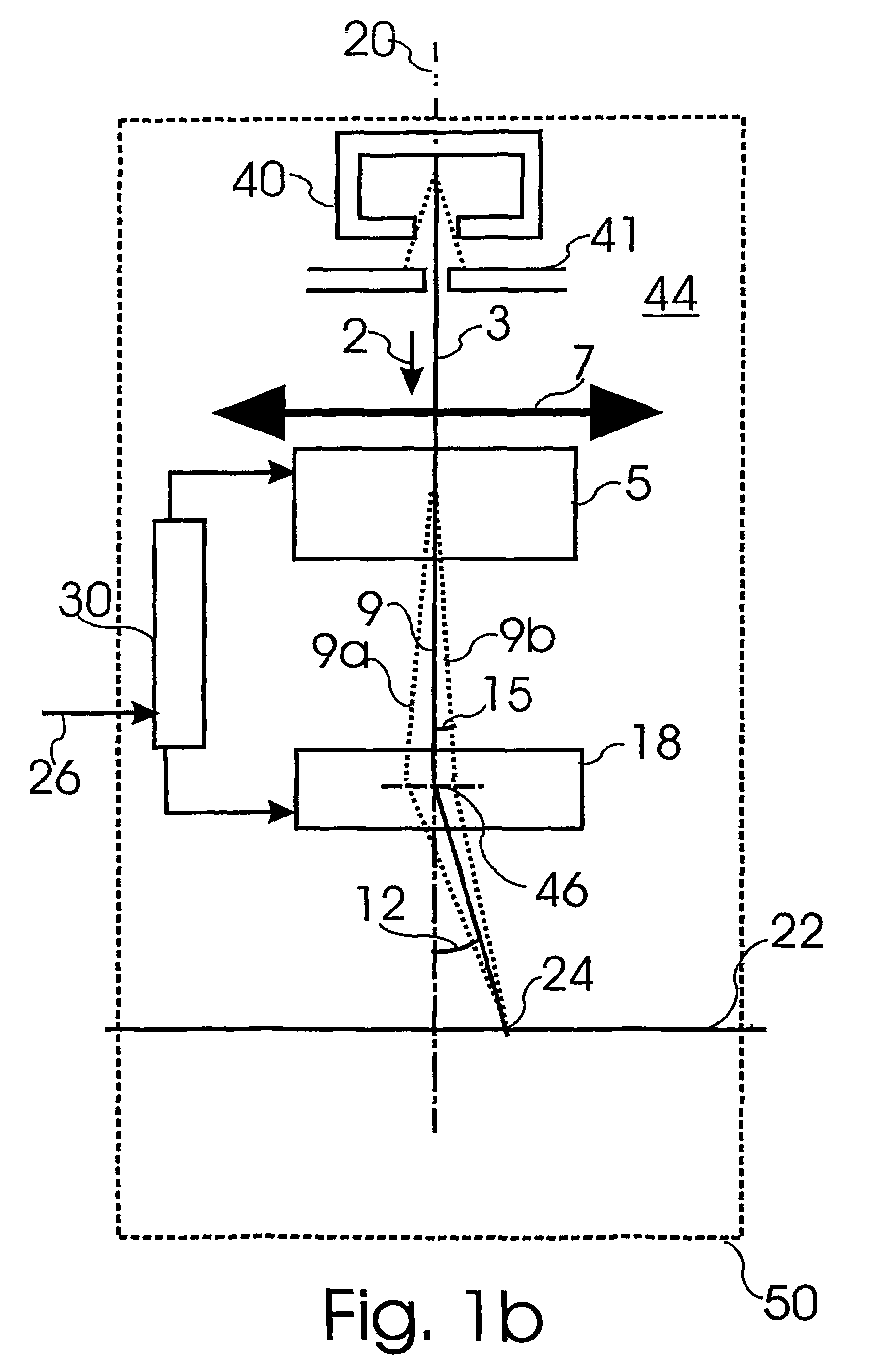
[0063]FIG. 1a shows schematically a first embodiment of a particle beam apparatus 50 according to the invention. In this embodiment, the deflector 38, as seen in particle beam direction, in behind the objective lens 7, whereas the corrector 5 is in front of the objective lens 7, as seen in particle beam direction. This embodiment allows the objective lens 7 to be positioned close to the target surface 22, since the deflector 18 can be realized as a simple electric or magnetic multipole without correction optics. Thus, the size of deflector is can be so small that it fits between the objective lens 7 and the target surface 22 even at a small working distance.

[0064]It is important to position the deflector 18 behind the objective lens 7 since this way, the particle beam 3 can be made to always pass along the optical axis of the objective lens 7. This way, chromatic or spherical aberrations of the objective lens 7 barely occur. Preferably, the optical axis of the objective lens 7 is ax...


PUM


Abstract

A particle beam apparatus and a device for an energy corrected deflection by a predetermined deflection angle of a particle beam coming in along a beam axis are disclosed, whereby the particle beam consists of charged particles with energy values scattered around a predetermined energy value. The device comprises a corrector, whereby the corrector, by means of a first electric field and a superimposed first magnetic field, deflects the charged particles depending on their energies, and whereby the direction of the charged particles with the predetermined energy value is maintained during the passage through the corrector. The device further comprises a deflector applied after the corrector, whereby the deflector, by means of a second electric field or by means of a second magnetic field, deflects the charged particles with the predetermined energy vague by the predetermined deflection angle away from the beam axis, whereby the deflector focuses the charged particles. Further, the device comprises a controller to control the corrector and the deflector.

Description

BACKGROUND OF THE INVENTION[0001]1. Field of the Invention[0002]The invention relates to a particle beam apparatus and a device for energy-corrected deflection of a particle beam of charged particles, and a method for energy-corrected deflection of a particle beam.[0003]2. Description of the Related Art[0004]Devices for deflection of particle beams of charged particles are utilized for particle beam apparatuses like, for example, electron microscopes, apparatuses of electron- or ion-lithography and for display apparatuses. For those applications, a particle beam of charged particles is to be deflected from an incoming direction to variable outgoing directions in order to reach different positions on a target surface.[0005]The deflection of particle beams from an incoming direction to an outgoing direction generally results from applying electric or magnetic fields which apply lateral forces to the particle beam. The electric or magnetic fields are generated by deflectors that includ...

Claims


Application Information

Patent Timeline
Patent Type & Authority Patents(United States)
IPC IPC(8): H01J3/14H01J37/147H01J37/153H01J37/21
CPCH01J37/153H01J37/147H01J37/30
Inventor BRUNNER, MATTHIASSCHMID, RALF
Owner AKT ELECTRON BEAM TECH
Why Eureka
Try Eureka