
Device and method for measurement of incident power and energy

a technology applied in the field of incident power and energy measurement devices, can solve the problems of inability to accurately measure low power and energy, inability to meet the measurement requirements, so as to reduce the number of measurement errors

Inactive Publication Date: 2006-12-26
OPHIR OPTRONICS
View PDF2 Cites 6 Cited by
  • Summary
  • Abstract
  • Description
  • Claims
  • Application Information

AI Technical Summary

Benefits of technology

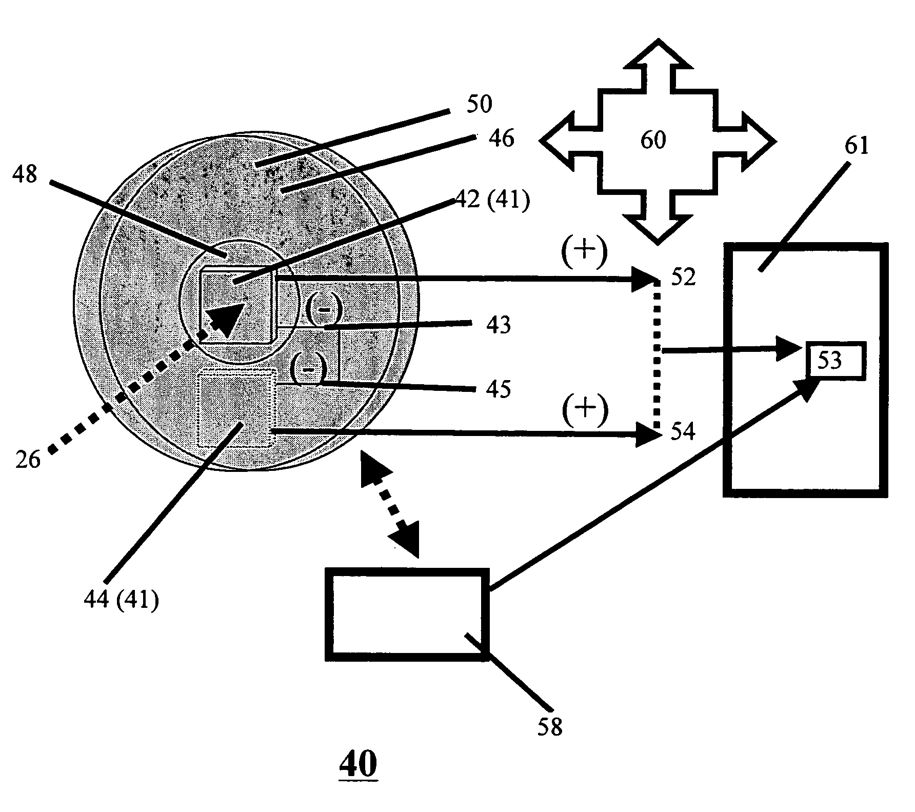
"The present invention provides a device and method for measuring the power and energy of a laser beam or other external energy source. The device includes a housing with an internal cavity and an aperture in fluid communication with the external environment. The housing has two sensors positioned in the internal cavity, one sensor positioned to receive the energy from the external source and another sensor positioned to receive only ambient energy. By subtracting the output of the ambient sensor from the output of the energy sensor, the device produces a corrected output signal that is more accurate than the original output signal. The method involves performing the same steps manually or automatically, and the device can be implemented using hardware or software. The invention reduces errors in measurement caused by variations in background radiation, providing a more accurate measure of laser power and energy."

Problems solved by technology

Devices of this type are inherently limited with respect to measurement of low powers and energies due to interference from ambient background radiation and temperature.
Since devices of this type measure a total temperature difference induced on the sensor from any source, the accuracy of the measurement is adversely affected because the light source being measured, changes in air temperature, and changes due to uneven radiation on the case of the measuring device all contribute to the total temperature difference.
Thus devices of this type introduce an unacceptable level of error into measurements, especially when measuring applied powers less than ˜1 mW.
However, this patent has, as an inherent limitation, a strict requirement for the measurement of light.

Method used


Image

  • Device and method for measurement of incident power and energy
  • Device and method for measurement of incident power and energy
  • Device and method for measurement of incident power and energy

Examples


Embodiment Construction

[0037]The present invention is of a device and method which can be employed for measurement of incident power and energy.

[0038]Specifically, the present invention reduces errors in measurement due to variations in background radiation.

[0039]The principles and operation of a device and method according to the present invention may be better understood with reference to the drawings and accompanying descriptions.

[0040]Before explaining at least one embodiment of the invention in detail, it is to be understood that the invention is not limited in its application to the details of construction and the arrangement of the components set forth in the following description or illustrated in the drawings. The invention is capable of other embodiments or of being practiced or carried out in various ways. Also, it is to be understood that the phraseology and terminology employed herein is for the purpose of description and should not be regarded as limiting.

[0041]The present invention is prima...


PUM

PropertyMeasurementUnit
powersaaaaaaaaaa
poweraaaaaaaaaa
poweraaaaaaaaaa

Abstract

Devices and methods for measurement of energy from a defined source having increased accuracy in measuring low energies. The device comprises a housing containing sensors. A first sensor receives energy from the source and produces a first output. A second sensor receives ambient energy only and produces a second output. Subtraction of the second output from the first output produces a more accurate corrected output. The method includes providing a housing containing a first sensor and a second sensor and directing energy from the defined source to a surface of the first sensor thereby causing the first sensor to produce a first output while only ambient energy from sources other than the defined source is applied to a surface of the second sensor which produce a second output that is subtracted from the first output producing a corrected output.

Description

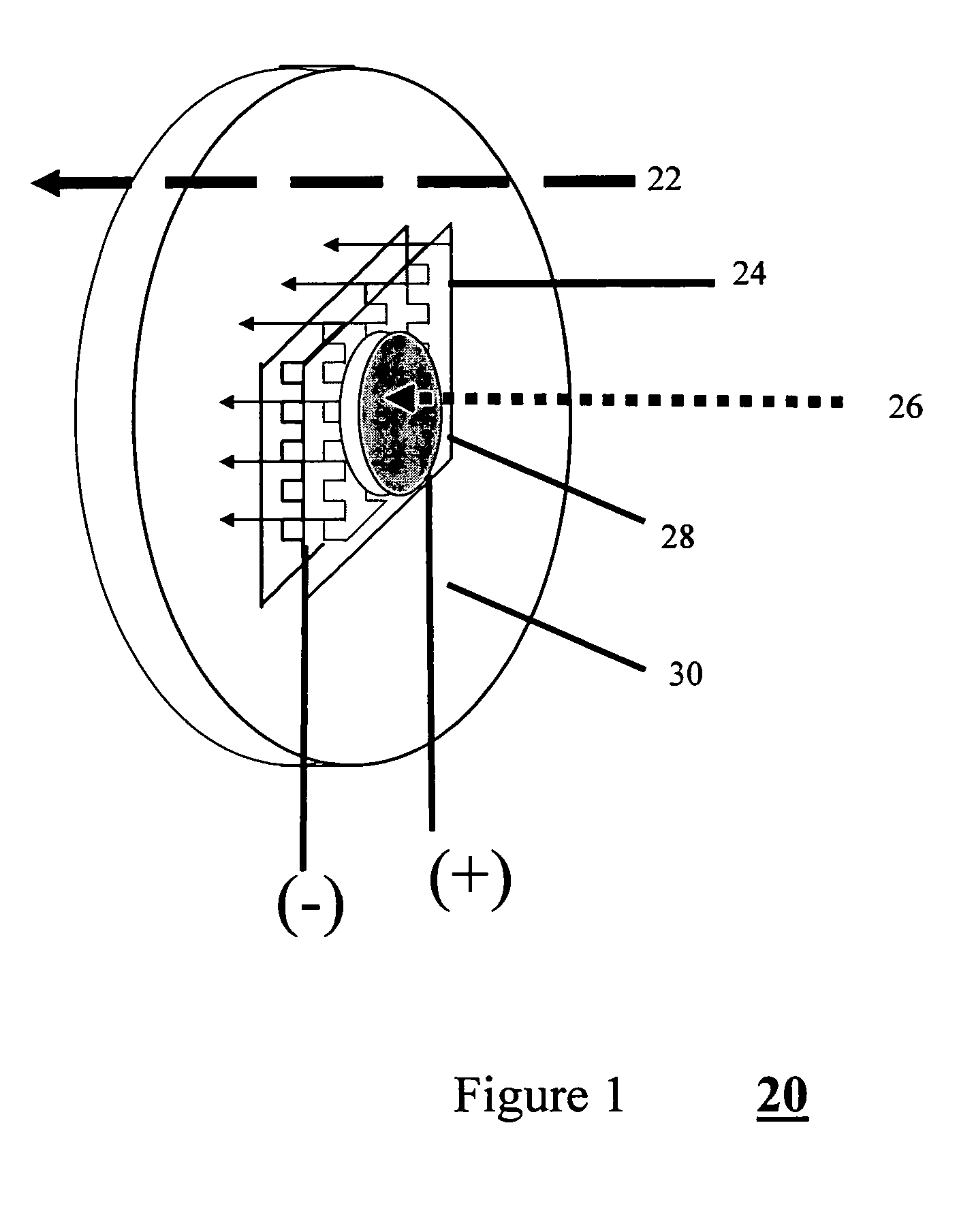
[0001]This application claims priority from U.S. Patent Application No. 60 / 544,231 filed on Feb. 13, 2004 and currently pending.FIELD AND BACKGROUND OF THE INVENTION[0002]The present invention relates to a device and method for measurement of incident power and energy and, more particularly, to devices and methods which reduce errors in measurement due to variations in background radiation.[0003]The term “power” as used herein refers to any measure of applied energy expressed as a function of time (e.g. 1 Watt=1 joule / s).[0004]Previously available thermal power meters based on the thermopile effect are used to measure the powers and energies of lasers or other light sources. These meters are based on the effect of heat flow through the sensor causing a temperature difference, which is converted by a thermopile into a voltage proportional to the power flowing through the device. FIG. 1 shows such a previously available device 20 based on use of a commercial thermoelectric cooler (TEC...

Claims


Application Information

Patent Timeline
Patent Type & Authority Patents(United States)
IPC IPC(8): G01J1/44G01J1/56H01J7/24G01K17/00G01K17/20
CPCG01K17/003G01K17/20
Inventor MIKLATZKY, EFRAIMGREENFIELD, EPHRAIM
Owner OPHIR OPTRONICS
Learn More