
Structural reinforcement strut for gas turbine case

a technology of structural reinforcement and gas turbine engine, which is applied in the direction of soldering media, application, soldering apparatus, etc., can solve the problems of increasing engine weight and manufacturing costs

Inactive Publication Date: 2010-11-04
PRATT & WHITNEY CANADA CORP
View PDF22 Cites 70 Cited by
  • Summary
  • Abstract
  • Description
  • Claims
  • Application Information

AI Technical Summary

Problems solved by technology

However, due to the stress concentration at leading and trailing edges between the struts and case walls, a significant number (referred to as high count) of struts are required in a structural turbine exhaust case, which increases the weight and manufacturing costs of engines.

Method used


Image

  • Structural reinforcement strut for gas turbine case
  • Structural reinforcement strut for gas turbine case
  • Structural reinforcement strut for gas turbine case

Examples


Embodiment Construction

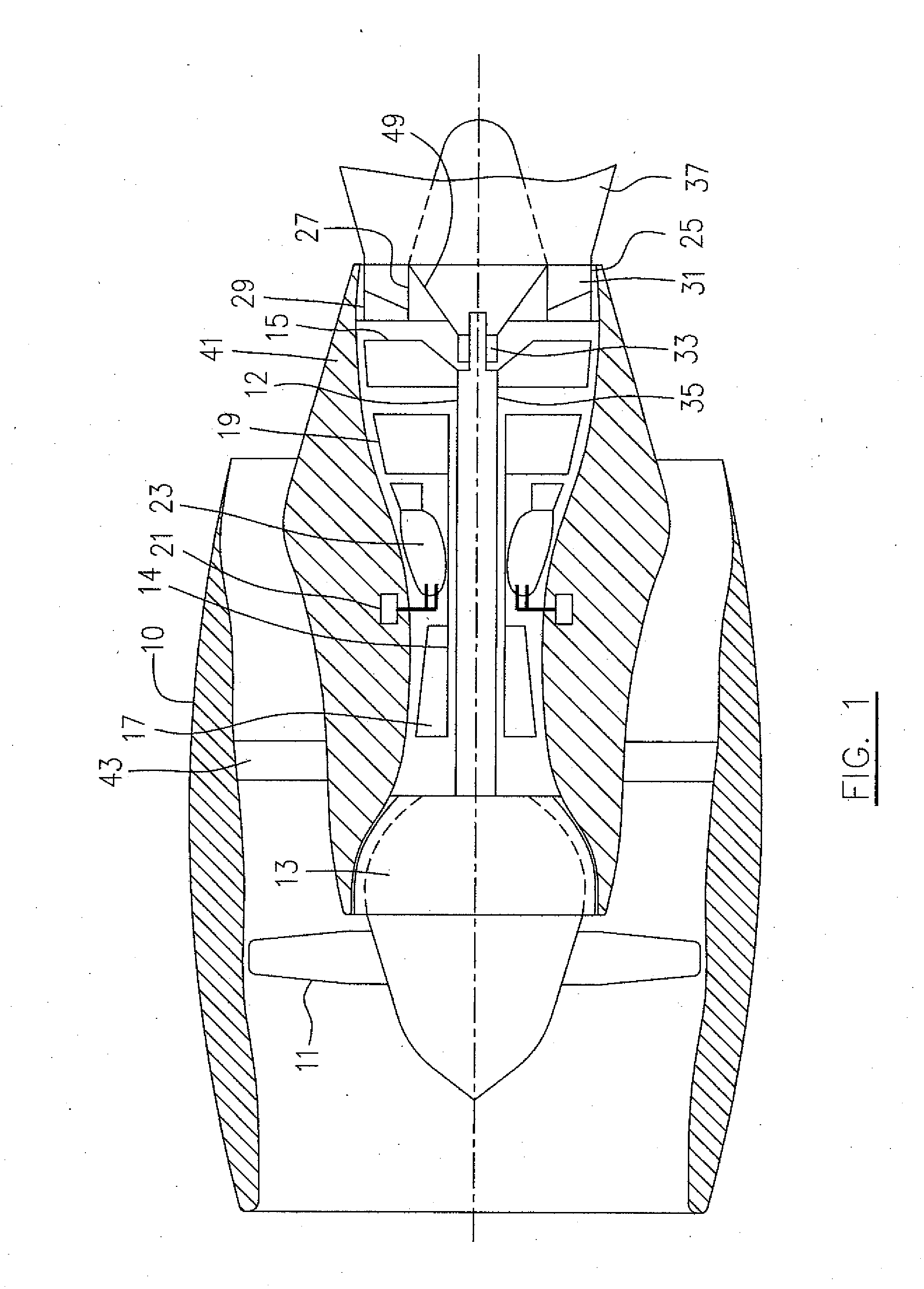
[0020]A turbofan gas turbine engine seen generally in FIG. 1 includes a housing or nacelle 10, a low pressure spool assembly seen generally at 12 which includes a fan 11, low pressure compressor 13 and low pressure turbine 15, a high pressure spool assembly seen generally at 14 which includes a high pressure compressor 17, high pressure turbine 19, a burner seen generally at 23 and fuel injecting means 21.

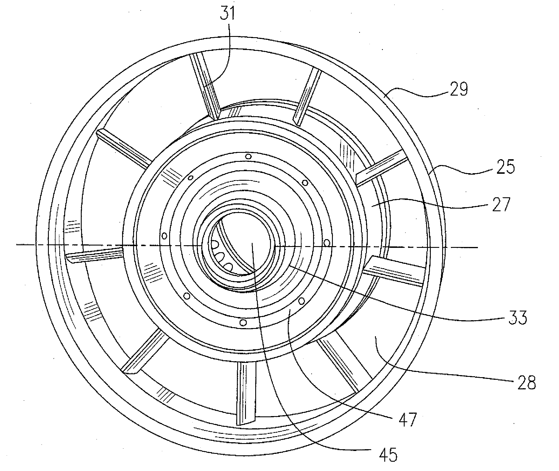
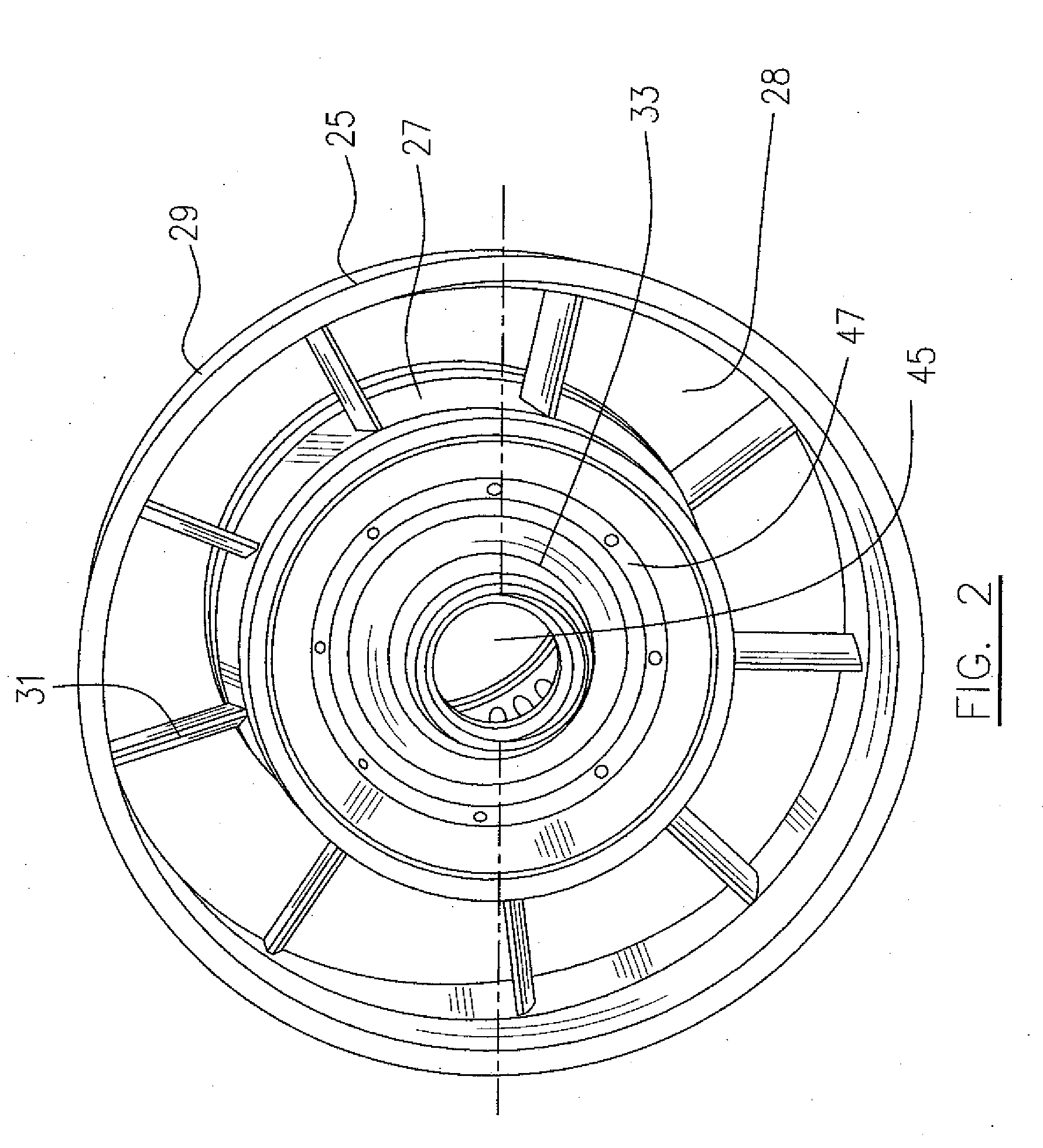
[0021]Referring to FIGS. 1 to 3, the turbofan gas turbine engine further includes a turbine exhaust case 25 which, as an example of the described concept includes an annular inner case portion 27 and an annular outer case portion 29 which defines an annular duct 28 therebetween, and a plurality of struts 31 circumferentially spaced apart, and radially extending within the annular duct 28 between the inner and outer case portions 27, 29, thereby structurally connecting same. A bearing housing 33 is co-axially connected to the inner case portion 27 for supporting an aft end of a main...


PUM

PropertyMeasurementUnit
lengthaaaaaaaaaa
thicknessaaaaaaaaaa
load stressaaaaaaaaaa

Abstract

A gas turbine engine case having a working fluid flow, includes inner and outer case portions defining an annular duct for directing the working fluid flow, and a plurality of struts positioned within the annular duct and extending between the inner and outer case portions. The struts are welded to the inner and outer case portions with a first weld along a peripheral line of the respective struts and with second weld, of fillet type, in selected locations for additionally connecting a portion of each strut to the respective inner and outer case portions.

Description

TECHNICAL FIELD[0001]The described concept relates generally to a case of a gas turbine engine.BACKGROUND OF THE ART[0002]A “non-structural” turbine exhaust case is typically used for gas turbines and is basically little more than an aerodynamic fairing which carries no additional load other than its own weight and any aerodynamic loading affected thereon. A “structural” turbine exhaust case on the other hand, not only supports its own weight and any aerodynamic loading, but also supports a bearing housing and bearing for a main spool of the engine, typically, the low pressure spool. Present state of the art structural turbine exhaust cases demand a configuration with an improved strength-to-weight ratio and sheet metal components such as struts welded to the turbine exhaust cases. However, due to the stress concentration at leading and trailing edges between the struts and case walls, a significant number (referred to as high count) of struts are required in a structural turbine ex...

Claims


Application Information

Patent Timeline
Patent Type & Authority Applications(United States)
IPC IPC(8): F02C7/20B23P11/00
CPCF01D25/162Y10T29/49321F01D25/24Y10T29/49323
Inventor FONTAINE, MIKEPAQUET, RENEFOURNIER, JEAN
Owner PRATT & WHITNEY CANADA CORP
Learn More