Gear-based continuously engaged variable transmission

Active Publication Date: 2010-11-04
ECONOMOU PANAYIOTIS
View PDF20 Cites 8 Cited by
  • Summary
  • Abstract
  • Description
  • Claims
  • Application Information

AI Technical Summary

Benefits of technology

[0024]The present invention demonstrates methods and devices for gear-ratio change, in which power can be transferred even during gear-ratio change and where the input and output gears are continuously engaged not necessarily through friction but through gears meshed together, thus minimizing wear and tear and abolishing possible slip. A variable transmission based on these methods or devices can avoid most of the drawbacks of variable transmissions of the prior art.
[0025]In addition, in embodiments of this invention where a differential assembly is coupled with the transmission in an appropriate way, it becomes possible for the destination of rotational motion to rotate, at varying speeds, in one or the other direction, or be kept stationary while the source of rotational motion is rotating at any speed. In the case of a motor vehicle this would represent forward and reverse motion as well as engine breaking and vehicle launch, all achieved with minimal wear and tear and no power loss. It also means that the vehicle could be poised

Problems solved by technology

However, torque is transferre

Method used


Image

  • Gear-based continuously engaged variable transmission
  • Gear-based continuously engaged variable transmission
  • Gear-based continuously engaged variable transmission

Examples


Embodiment Construction

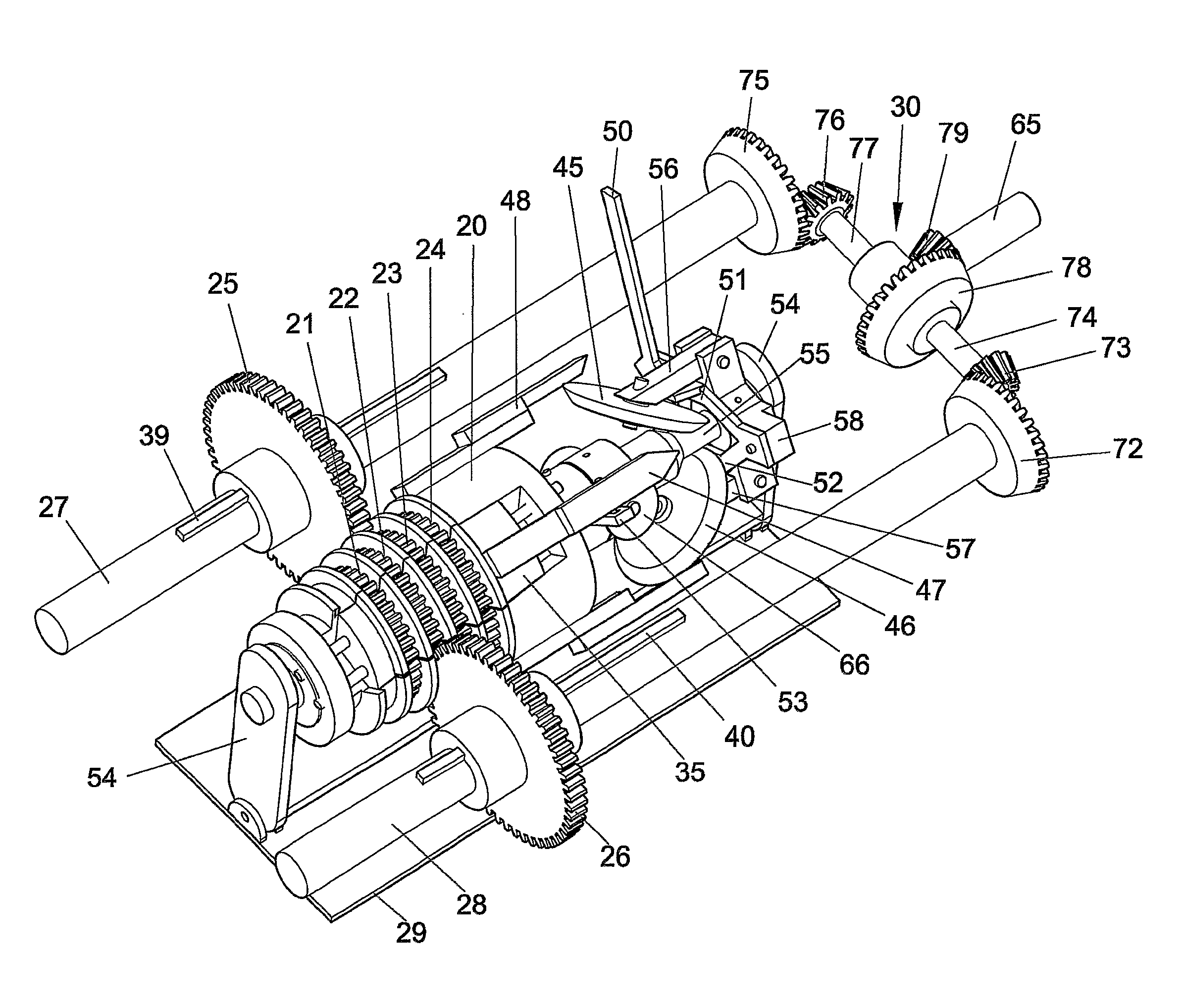
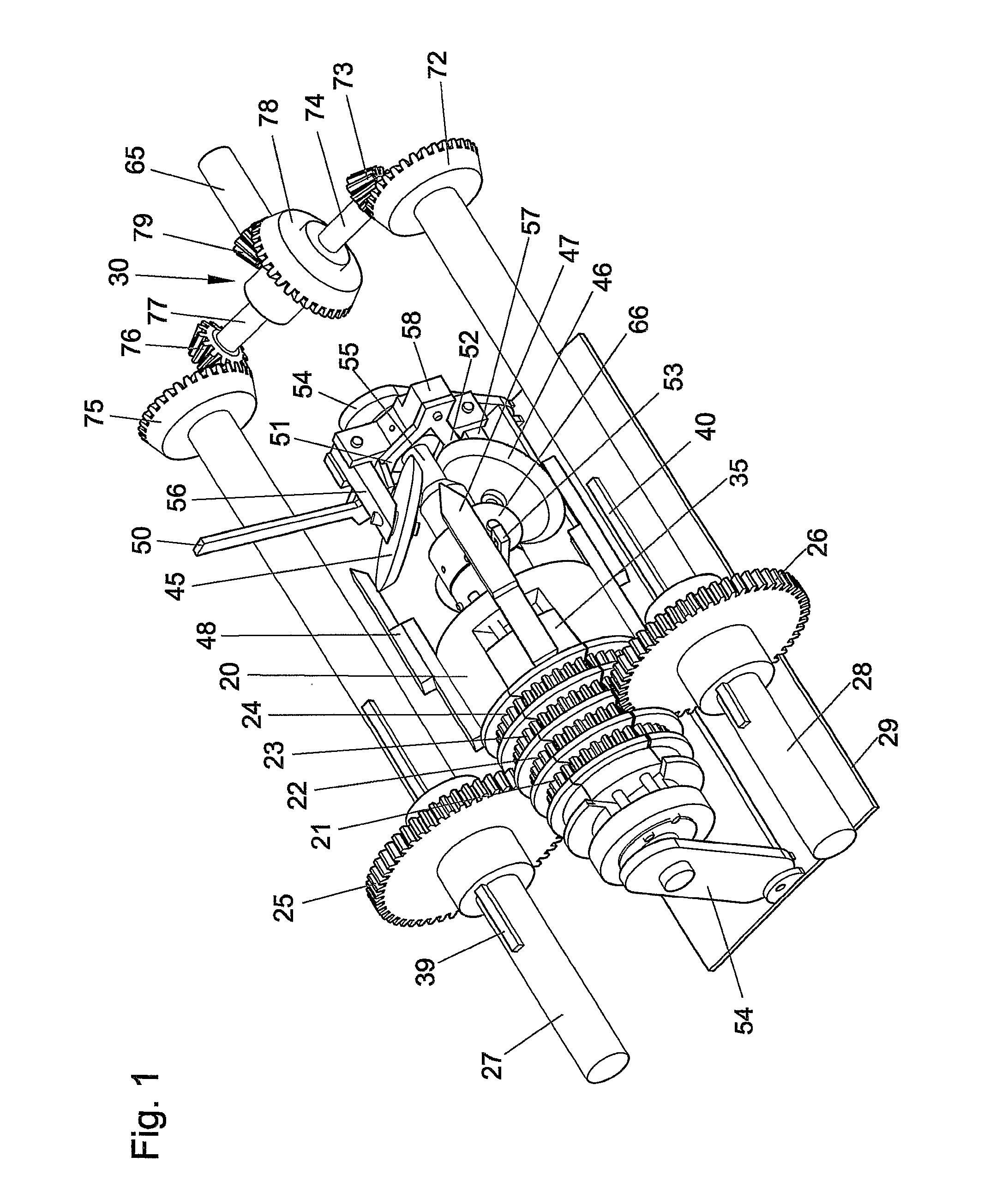
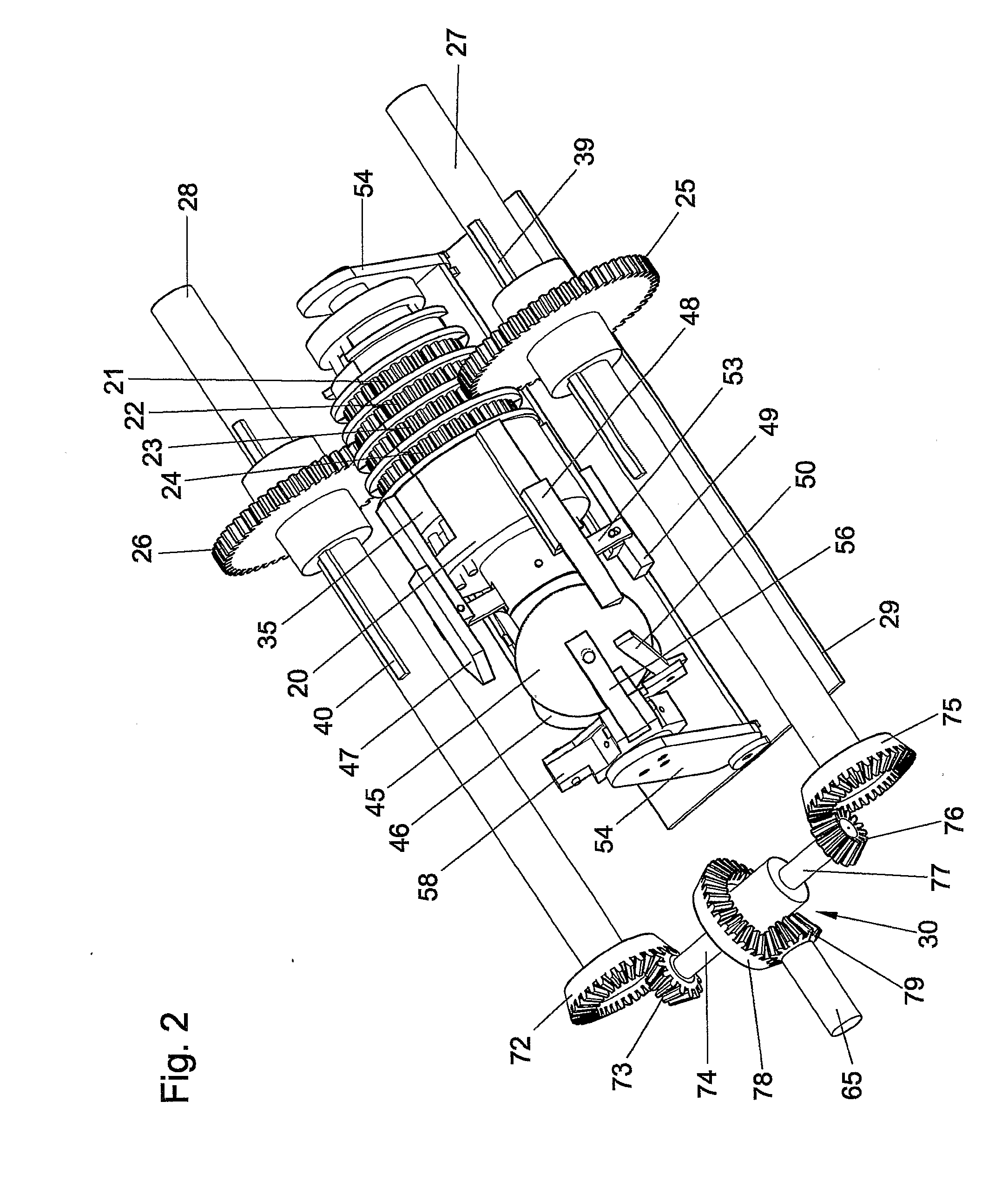
[0063]The embodiments described above were described just to demonstrate the main features of the invention. The invention is very versatile and the ideas and methods described can be embodied in a multiplicity of ways. In other embodiments, more forward and rear gear ratios can be offered by either involving more active composite gears or by employing more transmissions (embodiments of this invention) in series or in parallel or any combination between them. The step between each gear change can be increased by increasing the difference in diameter between each composite gear. This can be achieved by either increasing the difference in the number of teeth between each composite gear or by making the teeth larger. The step between each gear change can be decreased by doing the reverse. The step between each gear change can also be increased by arranging so that the elevator shifts by more than one step at a time.

[0064]The disclosed methods and devices can ensure gear-ratio change wi...


PUM

PropertyMeasurementUnit
Fractionaaaaaaaaaa
Timeaaaaaaaaaa
Angleaaaaaaaaaa

Abstract

A method is described for changing gear-ratio by displacing at least one part of the engaging surface of a composite gear (21) and aligning it to the engaging surface of another gear (22), thus permitting a complementary third gear (25) engaged to the engaging surface, to shift from one composite gear to a different composite gear, while being constantly engaged. The method can be employed in a device, which can be used to form a gear-based, continuously engaged, variable transmission. Such a transmission, enhanced by—being combined with a differential assembly and the appropriate gearing, can provide rotational motion at various speeds in one direction and the reverse direction as well as zero motion.

Description

TECHNICAL FIELD[0001]The invention relates to methods and devices to be used to modulate rotational speed or torque in any mechanical, electromechanical or electrical device or assembly, like for example a variable transmission, where there is a source of rotational motion and a final destination of that motion and there is the need for the rate of rotation at the destination to be variable. The invention further relates to methods and devices to be used to modulate rotational motion or torque anywhere where there may also be a need to provide a state of being, in which the source of rotation is providing rotational motion while the final destination is stationary and a state of being in which the final destination has to stop being stationary and start rotating.BACKGROUND ART[0002]The best example, where the needed rotational speed or torque is variable in relation to the supplied rotational speed or torque, is that of the motor vehicle. To achieve the above, motor vehicles usually...

Claims


Application Information

Patent Timeline
IPC IPC(8): F16H55/17B23P15/14
CPCF16H3/363Y10T74/1987Y10T29/49464
Inventor ECONOMOU, PANAYIOTIS
Owner ECONOMOU PANAYIOTIS
Why Eureka
Try Eureka