Plastic ammunition casing and method

a casing and ammunition technology, applied in the field of new cartridges, can solve the problems of poor quality of ammunition, and high cost of brass casings, and achieve the effect of reducing the cost of brass casings

Inactive Publication Date: 2010-11-04
TRIVETTE ROGER BLAINE
View PDF19 Cites 79 Cited by
  • Summary
  • Abstract
  • Description
  • Claims
  • Application Information

AI Technical Summary

Problems solved by technology

However, the use of brass casings for ammunition has several significant drawbacks.
First, the use of brass is costly, particularly when copper is in short supply, and that cost is passed along to the consumer.
Secondly, the brass component of bullets adds significant weight to the bullet, which creates a significant burden to those who must carry large amounts of ammunition, particularly including hunters, members of the military, and law enforcement.
Additionally, in order to prevent the deleterious effects that high humidity and other extreme environmental conditions may have on ammunition over time, costly protective measures must be adopted.
To overcome these disadvantages, other plastic bullet cases have been proposed, but each effort has resulted in its own set of problems.
Some plastic casings have failed because the plastic component could not withstand the high temperatures associated with repeated, rapid firings, thus resulting in a melting or softening of the plastic during use.
Other plastic ammunition casings are not strong enough to withstand the violent extraction action of the weapon, so that the casing fails structurally and fragment as it is being ejected from the weapon, which causes fragments of the casings then become lodged in the weapon.
Further, many of the plastic casings that have been proposed include complicated designs requiring multiple, time consuming manufacturing steps.
Thus, the plastic casings proposed to date have significant disadvantages, and have not been adopted on a mass commercial scale.

Method used


Image

  • Plastic ammunition casing and method
  • Plastic ammunition casing and method
  • Plastic ammunition casing and method

Examples


Embodiment Construction

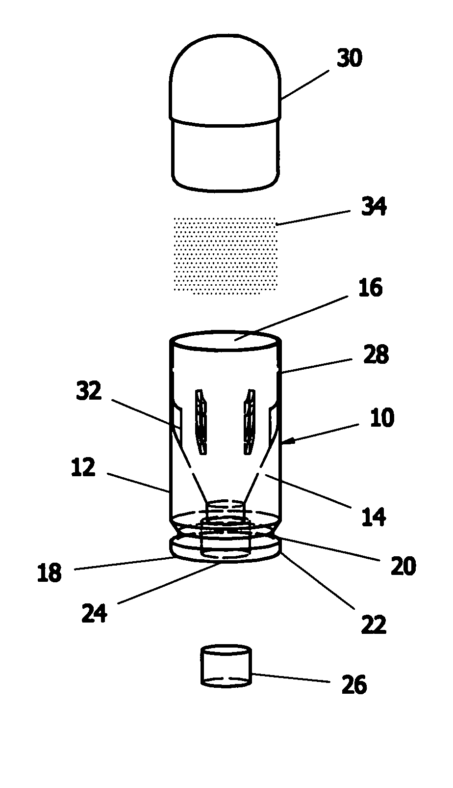
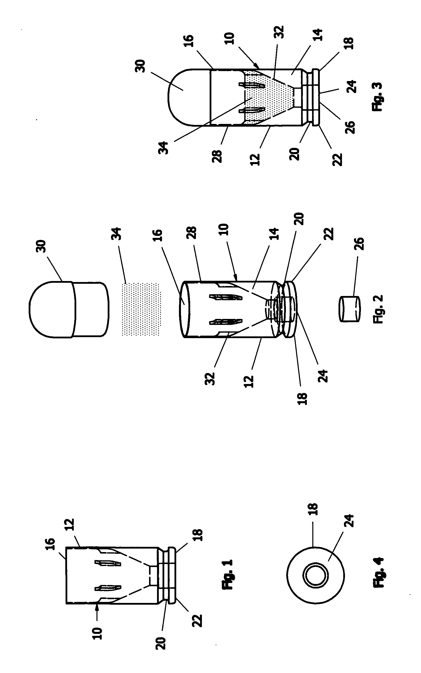
[0019]A first embodiment of a plastic casing for ammunition is shown in FIGS. 1-4. In this embodiment, the plastic casing 10 includes a tubular body 12 with a conical shaped section 14 on a lower portion of an inner surface, an open end 16 for receiving a projectile, and a base 18 comprising a substantially closed end having an annular groove 20 around the periphery of the body 12 at a lower end, thus defining an annular extracting rim 22. As shown in FIG. 4, an aperture 24 is provided at or near the center of the base 18 for insertion of a primer cap 26. The aperture 24 is formed so that it is in communication with the apex of the conical section 14 at the base 18 of the casing 10. It is also contemplated that another similar embodiment may be manufactured without the annular groove, but including an extracting rim around the periphery of the base.

[0020]FIGS. 1-3 show an integrally formed, polymeric casing 10 used in conjunction with pistol ammunition, wherein the casing 10 include...


PUM


Abstract

Ammunition having an integrally formed, polymeric casing is provided. Plastic casings for ammunition may be made using injection molding processes for combat ammunition, target ammunition and blanks. The casings, in one embodiment, include a hollow tubular member with an open end and a closed end having an aperture for a primer cap. The base of the casing includes a conical shape within the tube that narrows toward the base. An annular groove and an annular rim are disposed about an outer periphery of the base. Plastic casings may be utilized for ammunition cartridges used in pistols, rifles and shotguns, and are lighter and less expensive to manufacture than traditional brass casings. Further, the polymeric casings may include any desired colorants to distinguish different calibers of ammunition by color, and the spent casings may be recyclable.

Description

BACKGROUND OF THE INVENTION[0001]The present invention relates generally to novel cartridges for use in weapons of various types. More specifically, the present invention relates to a novel ammunition cartridge structure using a plastic casing, and a method for manufacturing the plastic casing.[0002]Heretofore, ammunition casings have been manufactured primarily by using brass. However, the use of brass casings for ammunition has several significant drawbacks. First, the use of brass is costly, particularly when copper is in short supply, and that cost is passed along to the consumer. Secondly, the brass component of bullets adds significant weight to the bullet, which creates a significant burden to those who must carry large amounts of ammunition, particularly including hunters, members of the military, and law enforcement. Additionally, in order to prevent the deleterious effects that high humidity and other extreme environmental conditions may have on ammunition over time, costl...

Claims


Application Information

Patent Timeline
Patent Type & Authority Applications(United States)
IPC IPC(8): F42B7/06F42B5/30
CPCF42B5/30F42B8/04F42B7/06
Inventor TRIVETTE, ROGER BLAINE
Owner TRIVETTE ROGER BLAINE
Why Eureka
Try Eureka